CHARGING SYSTEM - 4C-1390-823225--1 1096
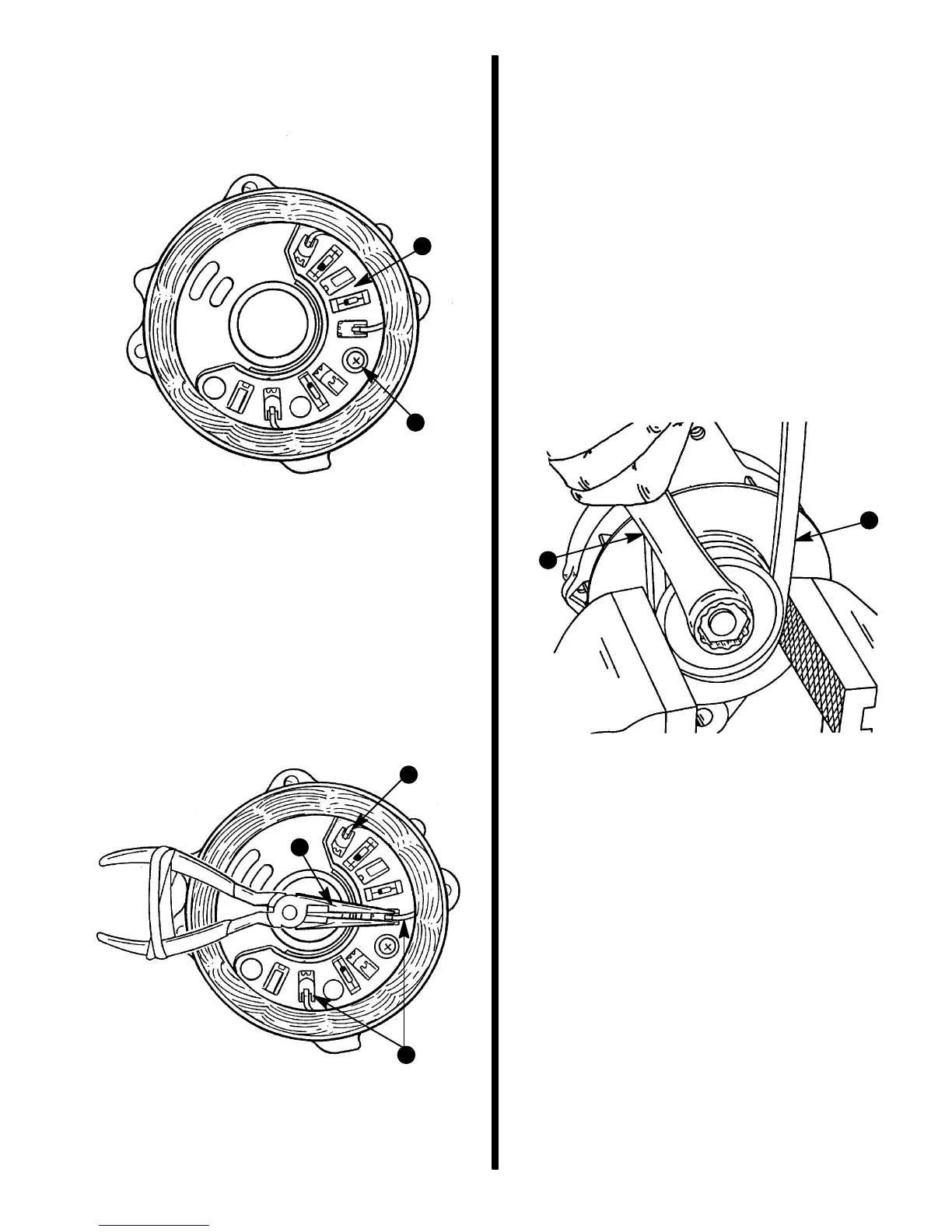
9. Turn end frame over (stator upward) and remove
one Phillips head screw which secures rectifiers
to end frame.
72826
b
a
a - Rectifier Assembly
b - Phillips Head Screw
10. Separate stator and rectifier assembly from rear
end frame using screwdriver slots.
11. Unsolder the three stator leads from the rectifier
heat sink. Place a needle nose pliers on diode ter-
minal between solder joint and diode body to help
prevent heat damage to diodes. Unsolder joints
as quickly as possible and allow diode terminal to
cool before removing pliers.
72827
a
b
b
a - Heat Sink
b - Stator Leads (3)
IMPORTANT: With alternator disassembled to
this point, stator, rectifier, diodes, and rotor may
be tested, as explained under “Component Test-
ing,” following.
IMPORTANT: DO NOT clamp vise on rotor pole
pieces when removing pulley nut (in next step),
as pole pieces may be distorted.
12. Remove pulley retaining nut by clamping pulley
in a vise (using an oversize V-belt or protective
jaws to protect pulley) and turning nut counter-
clockwise with a wrench. Remove lockwasher
and slide pulley and fan from shaft. If pulley is dif-
ficult to remove, it may be necessary to use a uni-
versal puller.
72828
b
a
a - Wrench
b - Over-Sized Belt To Protect Pulley

 Loading...