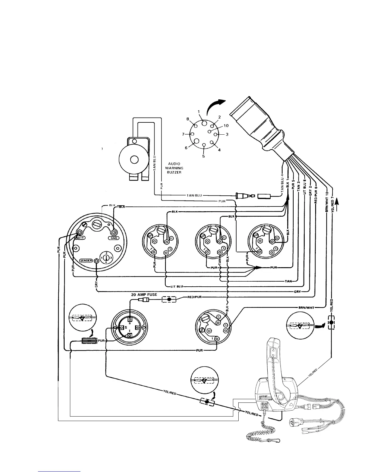
IGNITION
SWITCH
Tachometer
Oil
Pressure
Water
Temperature
Battery Meter
To Engine Harness
NOTE 1
TRIM
INDICATOR
NOTE 1
NOTE 1
NOTE 2
74046
WIRING DIAGRAMS - 4F-2590-823225--1 1096
MCM LATER STYLE CONTROLS AND AUDIO WARNING BUZZER
Refer to gauge manufacturer’s instructions for specific connections.
NOTE 1. Connect Wires Together with Screw and Hex
Nut; Apply Liquid Neoprene to Connection and
Slide Rubber Sleeve over Connection.
NOTE 2. Power for a Fused Accessory Panel May Be
Taken from This Connection. Load Must Not
Exceed 40 Amps. Panel Ground Wire Must Be
Connected to Instrument Terminal That Has an
8-Gauge Black (Ground) Harness Wire Con-
nected to it.

 Loading...