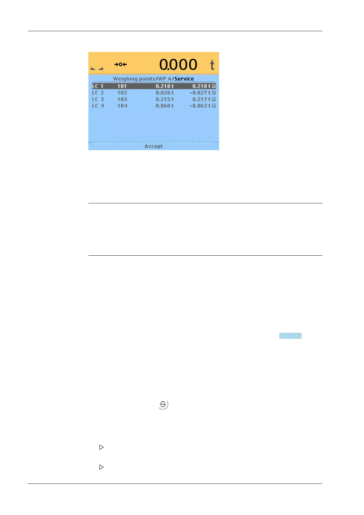
Item number, serial number, dead load and current weigh of connected load cells are
displayed.
7.17.9 Corner correction
7.17.9.1 Checking the corner load (dead load)
Note:
For scale structures with containers pay attention to the following:
- For asymmetric scale structures a corner correction is not necessary.
- But for symmetric scale structures corner correction may be required.
After assignment and calibration, the load cell positions have been defined clearly.
7.17.9.2 Mechanical corner correction
A Mechanical corner correction has to be carried out, if the load is not evenly distributed
over the load cells, e.g. if the platform is wobbling.
The dead load on the load cells can be corrected using shims. If two coupled platforms are
connected, corner load checking or installation of shims for the platforms must be
performed independently.
A fine calibration can be done by software corner correction, see Chapter
7.16.10.3.
7.17.9.3 Software corner correction
If the corners are loaded in succession, the same value should be displayed on the device
at all times. An excessive deviation almost always means that the scale is tilted or
indicates load cell force shunts.
If the signal deviations cannot be resolved by carefully leveling the scale, the software
must be calibrated.
The menu is accessible via
-[Weighing point]- [Weighing point A]- [Assign].
1. Press the [Modify] softkey.
2. Select and confirm [Corner correction].
3. Set the CAL weight on an area of the scale structure.
The position(e.g.: LC 4) is highlighted.
4. Confirm this position.
Is displayed by ☑.
X3 Process Indicator PR 5410 7 Getting started
EN-222 Minebea Intec