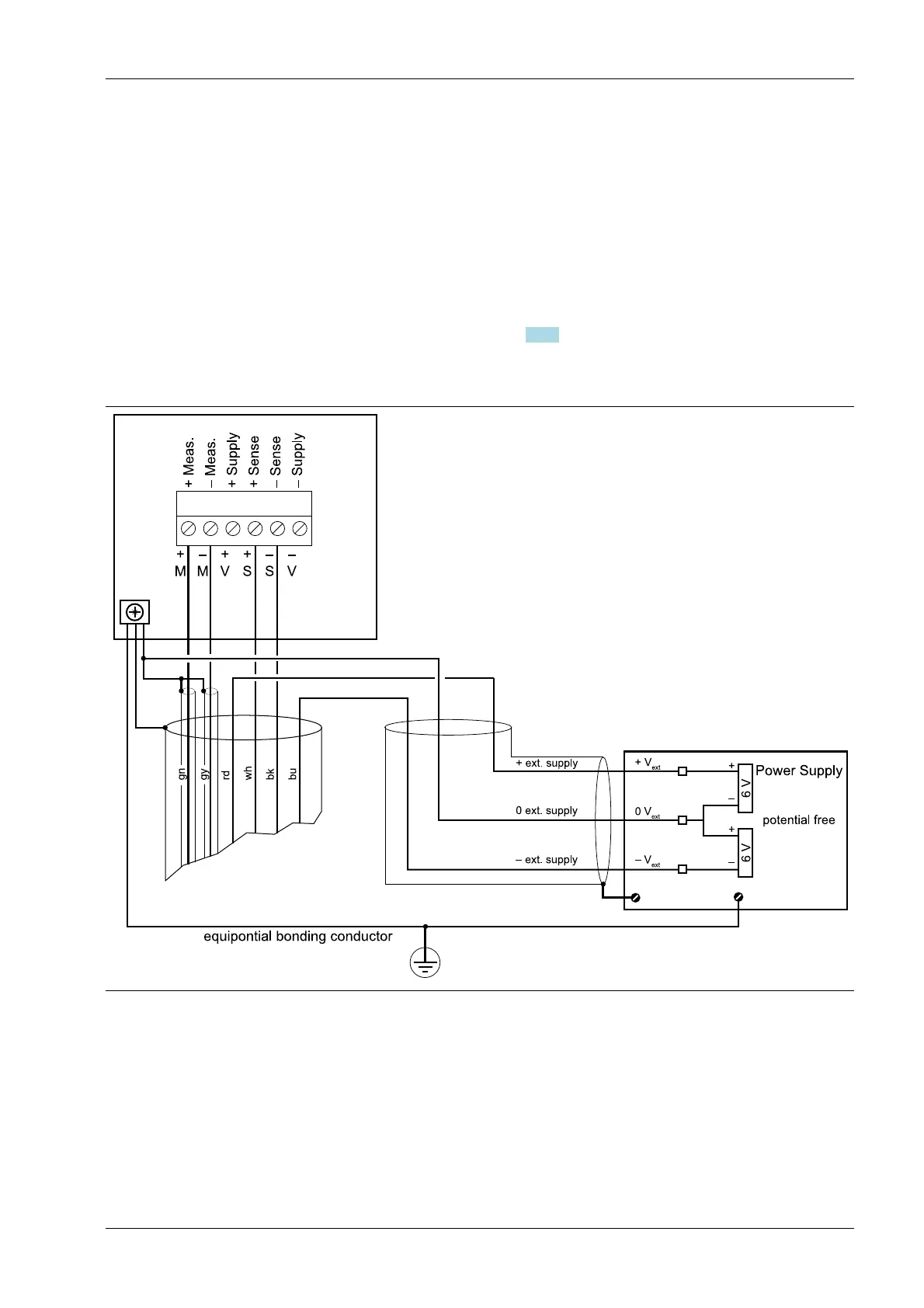
4.5.7 External supply to load cells
If the total resistance of the load cells is ≤75 Ω (e.g., more than 4 load cells with 350 Ω),
an external load cell supply is required. In this case, the internal supply is replaced by a
potential-free external supply.
The center of the external supply voltage (0 ext. supply) should be connected to the
device housing to ensure that the voltage reacts symmetrically to 0.
The internal supply is not connected.
If the external supply U
DC
<8 V (±4 V), a solder bridge (closed when delivered) must be
opened on the main board (see Chapter 4.5.8) to reduce the sense voltage U
DC
to below
approx. ±4 V.
Connection example
4 Device installation X3 Process Indicator PR 5410
Minebea Intec EN-51