Home
Minebea Intec
Measuring Instruments
X3
Minebea Intec X3 User Manual
4
of 1
of 1 rating
362 pages
Give review
Manual
Specs
To Next Page
To Next Page
To Previous Page
To Previous Page
Loading...
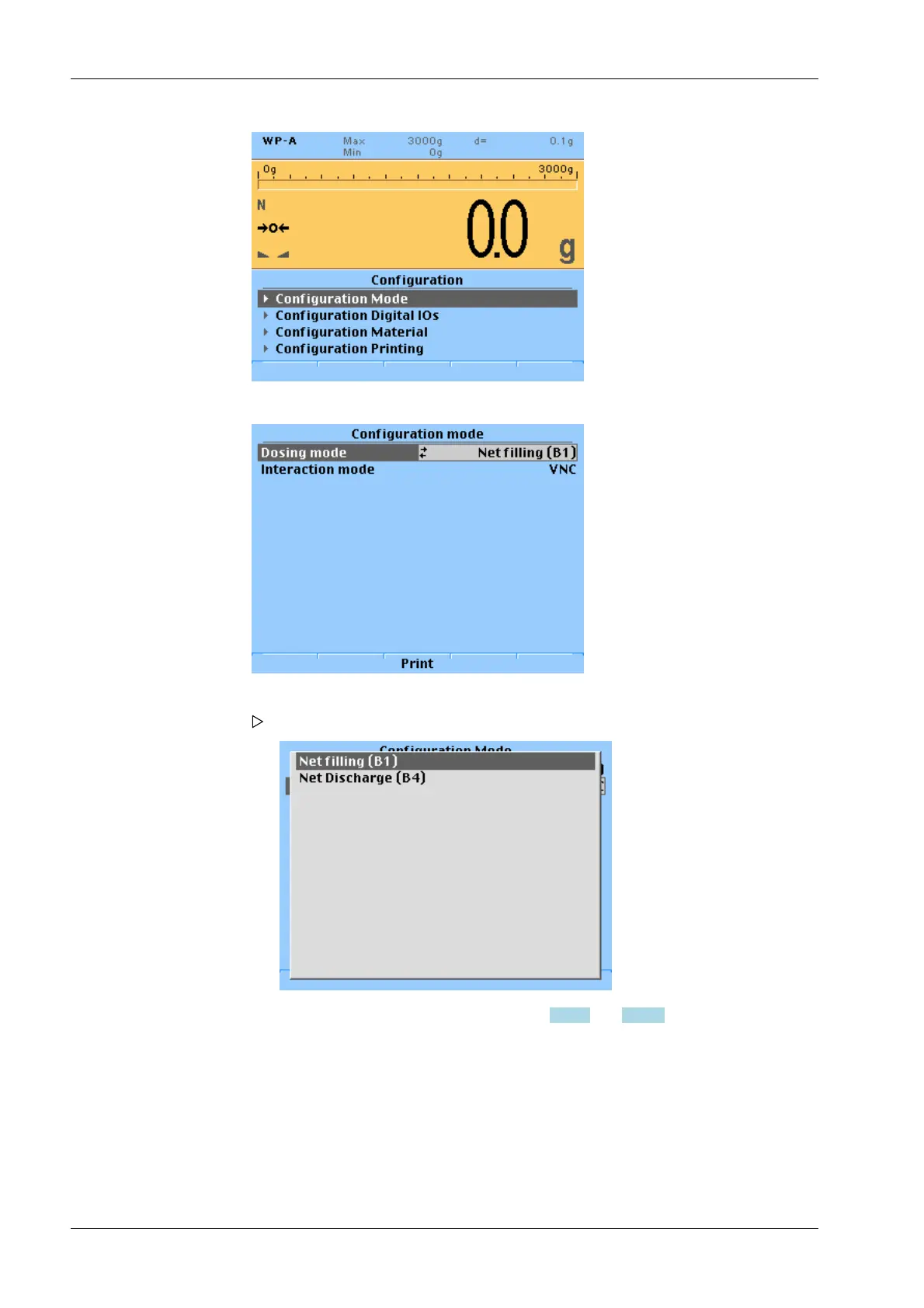
1.
Select
[Configuration mode]
and confirm.
2.
Select
[Dosing mode]
and confirm.
A selection window opens.
3.
Select the desired filling mode (see Chapters
8.4.1.1
and
8.4.1.2
) and confirm.
4.
Select
[Interaction mode]
and confirm.
X3
Process Indicator
PR
5410
8 Production
EN-276
Minebea Intec
277
279
Table of Contents
Table of Contents
3
Introduction
11
Read the Manual
11
This Is What Operating Instructions Look Like
11
This Is What Lists Look Like
11
This Is What Menu Items and Softkeys Look Like
11
This Is What the Safety Instructions Look Like
11
Hotline
12
Safety Instructions
13
General Notes
13
Intended Use
13
Initial Inspection
13
Before Operational Startup
13
Installation
14
Opening the Device
14
Supply Voltage Connection
14
Protective Ground Connection
15
RF Interference Suppression
16
Failure and Excessive Stress
16
Important Note
16
Repairs and Maintenance
16
General Information
16
Electrostatically Sensitive Parts
16
Replacing Fuses
17
Device Description
18
General Notes
18
Overview of the Device
18
Communication Protocols
19
Housing
19
General Notes
19
Dimensions
20
Control Panel Cut-Out
20
Display and Operating Elements
21
General Information
21
Overview
21
Display
21
Operating Elements
25
Overview of Connections
31
Plug-In Cards
32
Device Installation
34
General Notes
34
Mechanical Preparation
34
EMC-Compliant Installation
35
Connecting the Screens
35
Connecting the Equipotential Bonding Conductor
35
Hardware Construction
35
Mainboard
35
Display Board
37
Network Port
37
Interface
38
Digital Inputs
42
Digital Outputs
44
Connecting Analog Load Cells and Platforms
47
General Information
47
Connecting a Load Cell with a 4-Wire Cable
48
Connecting a Load Cell with a 6-Wire Cable
49
Connecting between 2 And8 Load Cells (650 Ω) Using a 6-Wire Connection Cable
50
Connecting Load Cells of Type Series PR 6221
51
Testing the Measuring Circuit
51
External Supply to Load Cells
53
Connection to Relay PR 1626/6X
54
Connecting an Analog Weighing Platform (CAP
56
Accessories
59
General Information
59
2× RS-232-Interface
61
1× RS-232 Interface and 1× RS-485 Interface
63
Canopen Interface
72
Connexx Module
74
Analog Inputs and Outputs
80
BCD Output (Open Emitter)
83
BCD Output (Open Collector)
87
Switch Settings
91
Output Modes
92
Opto-Decoupled Inputs and Outputs
93
Status Leds on Fieldbus Card
98
Profibus DP Interface
98
Interbus-S Interface
103
Devicenet Interface
108
CC-Link Interface
112
Profinet I/O Interface
114
Ethernet/Ip Interface
118
"Standard" Application
121
Functions
121
General Information
121
Display Functions
121
Easyfill" Application
122
Functions
122
General Information
122
Display Functions
122
Filling Mode
122
Application Menu [Start]
122
Getting Started
124
Power Failure/Data Backup/Restart
124
Power Failure
124
Data Backup
124
Overwrite Protection
124
Restart
125
Switching on the Device
126
Setting the Date and Time
127
Switching off the Device
128
Warm-Up Time
128
Configuring and Calibrating Using the Front-Panel Keys
128
Parameter Table (Setup)
128
Recalibrating the Internal Weighing Point Using the Front-Panel Keys
132
Changing the Dead Load of the Internal Weighing Point Using the Front-Panel Keys
135
Displaying the Calibration Data of the Internal WP Using the Front-Panel Keys
136
Reading out Calibration Data for WP Dead Load and Max Using the Front-Panel Keys
138
Search for Pendeo Load Cells and Set Dead Load Using the Front-Panel Keys
139
Creating a PIN Code Using the Front-Panel Keys
140
Deleting the PIN Code Using the Front-Panel Keys
141
Entering Fieldbus Parameters Using the Front-Panel Keys
142
Entering the Network Address Using the Front-Panel Keys
144
Displaying the Network Address Using the Front-Panel Keys
146
Displaying/Deleting Alibi Entries Using the Front-Panel Keys
147
Displaying/Deleting Alibi Entries
147
Deleting Alibi Entries
149
Finding and Connecting a Device with a Notebook/Pc
149
Finding and Connecting the Device Automatically in the Network
150
Searching the Device in the Network with "Indicatorbrowser
150
Resetting the Network Address
151
Operation Using VNC
152
Operation Via a Web Browser
153
System Setup
154
Serial Ports Parameter
154
Date & Time
155
Operating Parameters
155
Printing Parameter
155
Fieldbus Parameter
156
Network Parameter
156
Weighing Points
156
Limit Parameter
164
Digital I/O Parameters
165
Analog Output Parameter
165
Calibrating Internal Weighing Point
166
General Information
166
Displaying Calibration Data
166
Selecting the Calibration Mode
168
Setting Maximum Load
171
Determining the Scale Interval
171
Determining the Dead Load
172
Calibrating with Weight
173
Calibrating with MV/V
175
Calibrating with Load Cell Data (Smart Calibration)
177
Subsequent Dead Load Correction
178
Linearization
179
Calculating the Test Value
179
Saving the Calibration
180
Cancelling a Calibration
181
Parameter Input
182
Calibrating Xbpi-Scale
188
General Information
188
Parameters for Serial Interface
188
Parameters for the Xbpi-Weighing Function
189
Setting up an Xbpi Platform
190
Xbpi-Parameter Tables
193
Setting the Xbpi Dead Load
196
Xbpi Calibration with User Specified Weight
197
Xbpi Calibration with Automatic Weight Detection
199
Xbpi Calibration with Default Weight
199
Xbpi Calibration with Built-In Weight
200
Xbpi Linearization
201
Calibrating Digital Load Cells of Type "Pendeo
202
General Information
202
Selecting and Configuring RS-485 Interface
203
Selecting the Load Cell Type
204
Calibration Procedure
204
Searching Load Cells
205
Assigning Load Cells
207
Calibrating Load Cells
208
Assigning Load Cell Names
210
Service Function
210
Corner Correction
212
Terminating/Saving Calibration
213
Parameter Input
213
Subsequent Dead Load Correction
215
Displaying Weighing Point Serial Number
216
Calibrate Load Cells Incl. Connexx Module
216
General Notes
216
Selecting the Load Cell Type
216
Calibration Procedure
217
Search for Load Cells
217
Assign Load Cells
219
Calibrate Load Cells
220
Assign Load Cell Name
222
Service Function
222
Corner Correction
224
Terminating/Saving Calibration
225
Parameter Input
225
General Parameter Settings
229
Selecting and Configuring Serial Interfaces
229
Date and Time
238
Operating Parameters
239
Print Parameters
241
Fieldbus Parameters
242
Network Parameters
245
Configuring Limit Values
246
Configuring Digital Inputs
252
Configuring Digital Outputs
255
Configuring Analog Output
260
System Information
261
Displaying the Version
262
Displaying the Status
263
Showing Hardware Options
264
Displaying the Alibi Memory
265
Displaying Pendeo Data
266
Show Connexx Data
268
Production
271
General Notes
271
Configuration Using the Front-Panel Keys
271
Configuring Production Mode Using the Front-Panel Keys
271
Configuring Interaction Mode Using the Front-Panel Keys
272
Configuring Digital Inputs and Outputs Using the Front-Panel Keys
272
Configuring Printout Using the Front-Panel Keys
274
Starting the Application
277
Configuration Via a Notebook/Pc
277
Configuring Production Mode
277
Configuring Digital Inputs and Outputs
281
Configuring Material
283
Configuring Printout
285
Filling
287
Extended Functions
289
Hardware Test
289
Display Test
289
Front-Panel Key Test
289
Serial Interfaces
290
Inputs and Outputs
290
Functions Via the WEB Site
296
General Information
296
Displaying Weighing Points in a Table
297
Configuration Printout
297
Log Files
298
Screenshots
299
Error Log
299
Alibi Memory
300
Configuration Data
303
Resetting the Device to the Factory Settings Using the Front-Panel Keys
304
Resetting the Device to the Factory Settings
305
Updating New Software with Flashit
306
Updating in Network with a DHCP Service
306
Updating Via a Point-To-Point Connection with DHCP Service
308
Updating with a Fixed IP Address
309
Modbus Protocol
313
General Description
313
SPM Data in PR 1612 Modbus Mode
313
SMA Protocol
315
General Information
315
Fieldbus Interface
316
General Notes
316
Scale Protocol (8-Byte) for the "Standard" Application
316
Data Exchange Range
317
Reading and Writing Data with Function Numbers
319
Reading and Writing Bits Directly
321
Waiting for the Result of the Action
321
Function Numbers
322
Example: Reading the Gross Weight
327
Special Note for Devicenet and Ethernet IP
328
Filling Protocol (64-Byte) for the "Easyfill" Application
328
Write Window (Input Area)
328
Read Window (Output Area)
328
Indicator Functions
329
Filling Functions
329
Setup of the Fieldbus Interface
331
Spm
337
General Information
337
Elementary Data Types
337
Addressing
338
System Data
338
Repairs and Maintenance
344
Repairs
344
Battery for Date/Time
344
Changing the Battery for Date/Time
344
Changing Fuse
345
Maintenance
345
Soldering Work
345
Cleaning
346
Disposal
347
Error Messages
348
Error Messages Measuring Circuit
348
Error Messages for Xbpi Scales
349
Error Messages for Pendeo Load Cells
349
Error Messages During Calibration
350
General Error Messages
352
Error Numbers @ "LAST_ERROR
354
Weighing Point Error
354
Error in the "Easyfill" Application
354
Technical Data
356
Note on Using "Free Software
356
Decoding the Serial Number
356
General Data
356
Backup for Date/Time
356
Supply Voltage Connection 230 V AC
356
Supply Voltage Connection 24 V DC
356
Effect of Ambient Conditions
357
Ambient Conditions
357
Electromagnetic Compatibility (EMC)
357
RF Interference Suppression
357
Weighing Electronics
358
Load Cells
358
Principle
358
Accuracy and Stability
358
Sensitivity
359
Connecting Cables
359
Mechanics
359
Design
359
Weights
359
Documentation on the CD Included
359
Appendix
360
Replacement Parts
360
Test Connector
361
Certificates
361
4
Based on 1 rating
Ask a question
Give review
Questions and Answers:
Need help?
Do you have a question about the Minebea Intec X3 and is the answer not in the manual?
Ask a question
Minebea Intec X3 Specifications
General
Brand
Minebea Intec
Model
X3
Category
Measuring Instruments
Language
English
Related product manuals
X3 Process Indicator PR 5410
340 pages
Minebea Intec PR 5310
200 pages
Minebea Intec PR 5310/12
200 pages