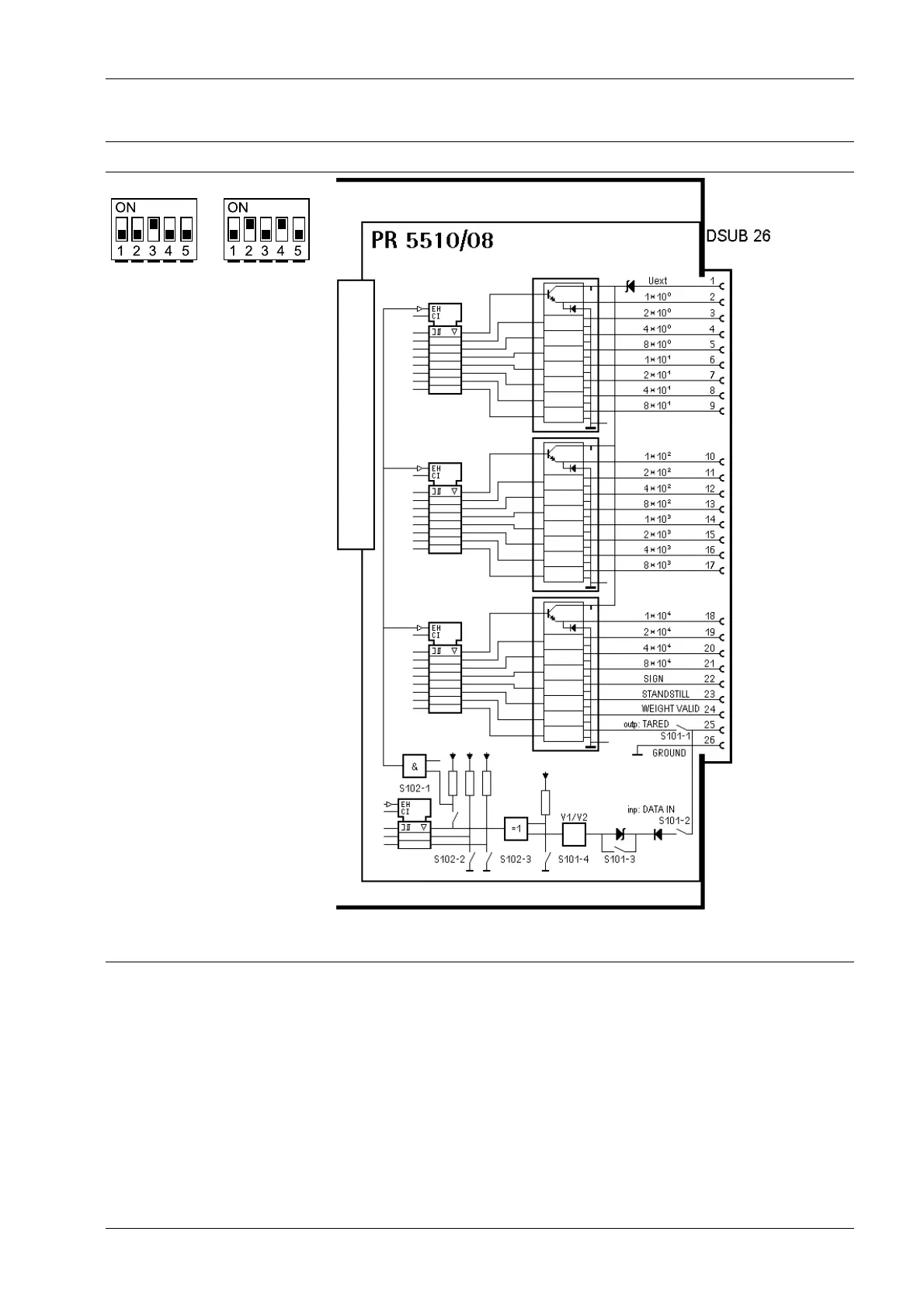
Switch for input PR 5510/08 block diagram
Factory setting:
S102
Factory setting:
S101
An external power supply is required: PIN 1 (Uext), reference potential
PIN 26 (GND)
4.6.7.1 Outputs
The outputs for PR 5510/08 (PIN 2…24) work with a shared power supply at the collector
as a reference potential and open emitter outputs.
A non-active output is highly resistant.
A voltage of approx. 1.7 V, which is less than the supply voltage, is applied to an active
output.
The load to be connected is between the outputs (PIN 2…24, 25) and GND (PIN 26).
4 Device installation X3 Process Indicator PR 5410
Minebea Intec EN-83