6-2/END GROUND iPASOLINK EX/A
GGS-000546-01E iPASOLINK EX Advanced: INSTALLATION
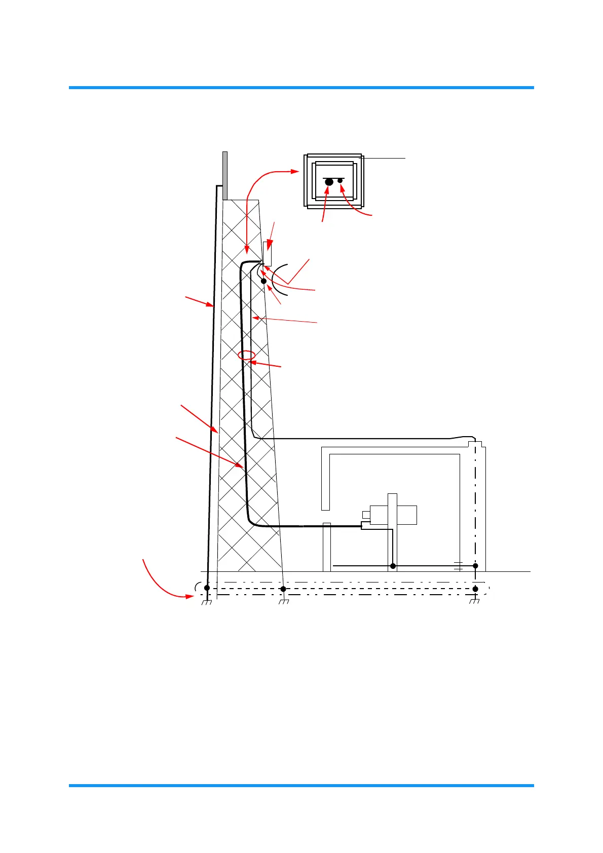
Figure 6-2 Grounding Method (Example – 2/2)
NOTES:
* NEC recommends that the equipment should be connected to earth line
as NEC’s standard installation.
EP Earth Ground Point of tower
LIGHTNING ROD
GROUNDING WIRE
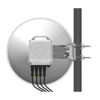
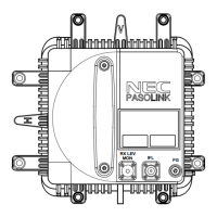
iPASOLINK
GROUNDING WIRE*
POWER CABLE
GROUND
LEVEL
(away from tower)
Grounding Resistance
EP
It lets through the center of the steel
tower as much as possible.
Tower
EX/A
should be less than 10 Ohms)
(Grounding Resistance of
Tower should be less than
10 ohms.)
This is the buried grounding
wire. This type of wire is
naked (not insulated),
which is recommended.
Grounding wire for iPASOLINK EX/A should be
connected to the nearest EP of the tower.
(Grounding Resistance should be less than 10 ohms)
Let the cables run through inside of steel tower.
GROUNDING WIRE
POWER CABLE
GROUNDING TERMINAL