ADJUST ANTENNA ANGLE 8-9
iPASOLINK EX Advanced: INSTALLATION GGS-000546-01E
Safety distance should be calculated according to the conditions of installation site.
Following show the calculation examples:
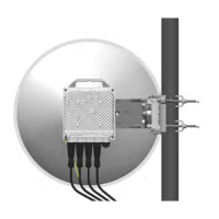
Calculation Example 1 (Front Side of Antenna)
iPASOLINK EX/A = +18 dBm
Antenna Diameter = 0.6 m
Antenna Gain = 52 dBi
Distance = 9.0 m
Output Power Density : S = 0.982 mW/cm
2
1 mW/cm
2
Limit: Output Power Density S = 10 (W/m
2
) * = 1 (mW/cm
2
)
*:
COUNCIL RECOMMENDATION (1999/519/EC) of 12 July 1999 on the
limitation of exposure of the general public to electromagnetic fields (0 Hz to 300 GHz)
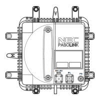
Calculation Example 2 (Rear Side of Antenna)
iPASOLINK EX/A = +18 dBm
Antenna Diameter = 0.6 m
Antenna Gain = –16 dBi
Distance = 0.004 m = 4.0 mm
Output Power Density : S = 0.788 mW/cm
2
1 mW/cm
2
Limit: Output Power Density S = 10 (W/m
2
) * = 1 (mW/cm
2
)
*:
COUNCIL RECOMMENDATION (1999/519/EC) of 12 July 1999 on the
limitation of exposure of the general public to electromagnetic fields (0 Hz to 300 GHz)
The safety distance that is obtained by the conditions above and is below the value
defined by
COUNCIL RECOMMENDATIN (1999/519/EC) of 1 mW/cm² is:
Front Side of Antenna (X) 9.0 m
Rear Side of Antenna (Y) 0.004 m = 4.0 mm