Issue 1.2 UNIVERGE SV9100
4 - 52 Installing the SV9100 Blades
4.5.4 Connectors
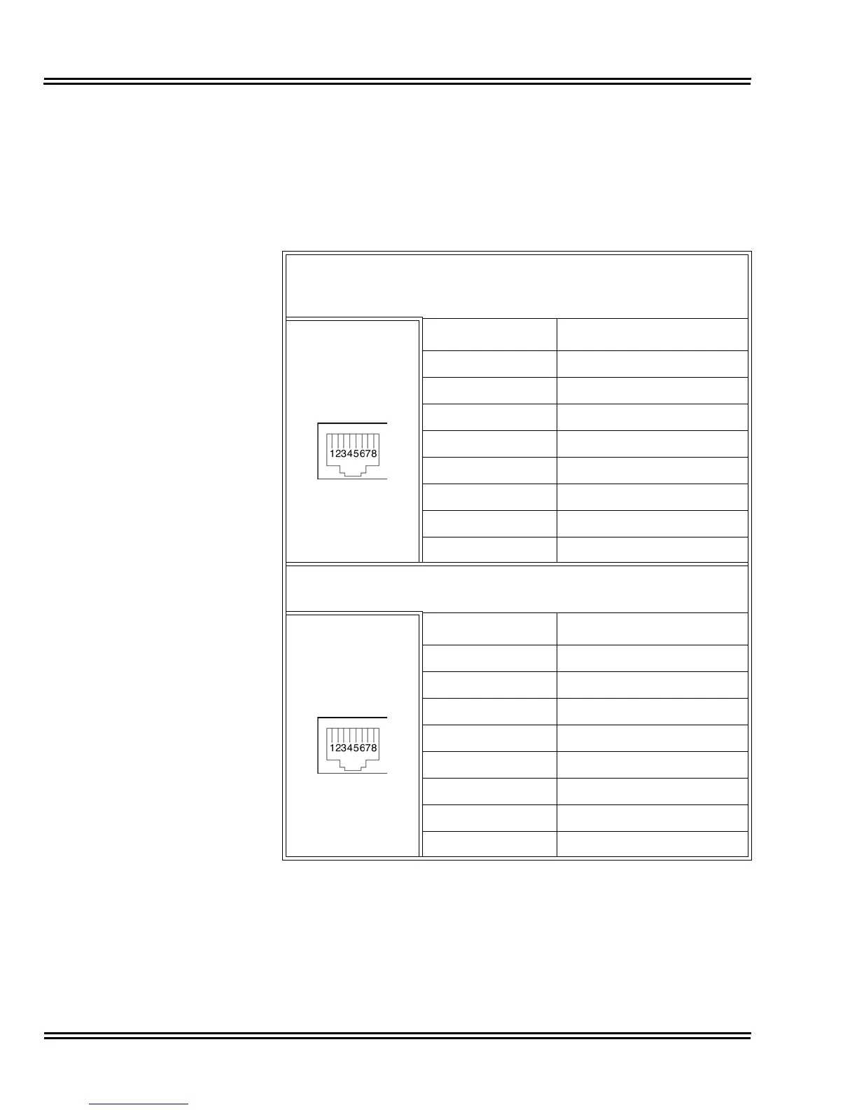
Table 4-25 GCD-LTA RJ61 Cable Connector Pin-Outs on page 4-52
shows the pin-outs for the RJ-61 connector. Refer to Figure 4-13
GCD-LTA Blade on page 4-49 for an illustration showing the location
of the connectors on the GCD-LTA blade.
Table 4-25 GCD-LTA RJ61 Cable Connector Pin-Outs
RJ61 Cable Connector
Digital: CN101 (ports 1~4)
Digital: CN102 (ports 5~8)
Pin No. Connection
1 T4/T8 (Tip for port 4 or 8)
2 T3/T7 (Tip for port 3 or 7)
3 T2/T6 (Tip for port 2 or 6)
4 R1/R5 (Ring for port 1 or 5)
5 T1/T5 (Tip for port 1 or 5)
6 R2/R6 (Ring for port 2 or 6)
7 R3/R7 (Ring for port 3 or 7)
8 R4/R8 (Ring for port 4 or 8)
RJ61 Cable Connector
Analog: CN201 (ports 1~2)
Pin No. Connection
1–
2–
3 T2 (Tip for port 2)
4 R1 (Ring for port 1)
5 T1 (Tip for port 1)
6 R2 (Ring for port 2)
7–
8–

 Loading...


