Issue 1.2 UNIVERGE SV9100
6 - 2 Installing SV9100 Optional Equipment
The PGD(2)-U10 ADP connects to any available digital extension port. The
terminal connections made within the PGD(2)-U10 ADP and the jumper
settings determine what features are used for each circuit.
2.2 LED Indications
2.3 Setting up PGD(2)-U10 ADP Connections
If the PGD(2)-U10 ADP is to be wall mounted, all the cable connections
should be made first.
For the module to ID correctly after setting the jumpers, set the circuit type
to 0 for the module port in Program 10-03-01 prior to connecting the line
cord to the PGD(2)-U10 ADP.
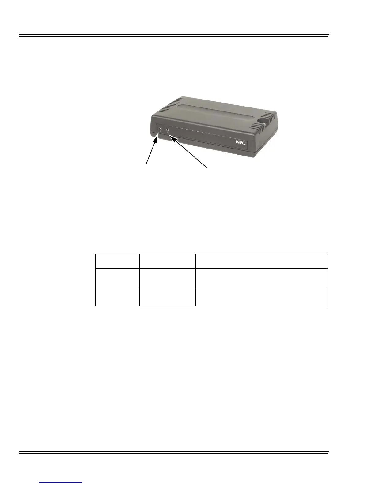
Figure 6-1 PGD(2)-U10 ADP
Table 6-1 PGD(2)-U10 ADP LED Indications
LED Indication Note
LED 1 Green LED when
CH1 in use.
Flashing green LED indicates dipswitch setting
and programming for CH1 is conflicting.
LED 2 Green LED when
CH2 in use.
Flashing green LED indicates dipswitch setting
and programming for CH2 is conflicting.

 Loading...


