UNIVERGE SV9100 Issue 1.2
System Hardware Manual 4 - 71
Four (4DIOPU) DID trunk circuits or four OPX circuits
Two Blade status LEDs
Table 4-36 GCD-4DIOPB Maximum Upgrade Capacities provides
the maximum capacities for the GCD-4DIOPB blades when they are
upgraded.
5.5.2 Installation
The GCD-4DIOPB can be installed in any universal slot.
5.5.3 LED Indications
LED indications for the GCD-4DIOPB are listed in Table 4-37
GCD-4DIOPB LED Indications. Each LED is listed with its
associated function and LED and Operational status. Refer to Figure
4-18 GCD-4DIOPB Blade on page 4-70 for the location of the LEDs
on the blade.
Table 4-36 GCD-4DIOPB Maximum Upgrade Capacities
19” Chassis
with CPU
19” Chassis
without CPU
19” Chassis
x4
Networked
Chassis
5 6 23 50
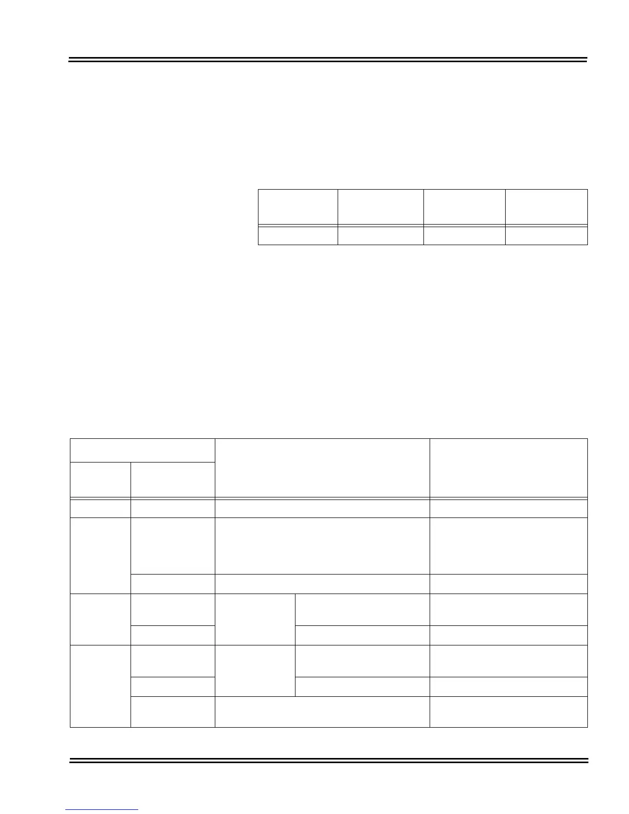
Table 4-37 GCD-4DIOPB LED Indications
LED Indication
Operation Status Remarks
Live LED
(Green)
Busy LED
(Red)
On On System Initializing –
Flash (1s) On The assignment of the unit is refused.
When you exceed the system
capacity.
When the main software
version is not matched.
Flash (1s) Trouble found during self-diagnostics. –
Flash
(100ms)
On
Normal
Operation
A Channel is busy (use
another from CH1 ~ CHx).
–
Off All channels are idle. –
Off
On
Unit Busy
A Channel is busy (use
another from CH1 ~ CHx).
–
Off All channels are idle. –
Flash (100ms
On/Off)
Downloading firmware. –

 Loading...


