Issue 1.2 UNIVERGE SV9100
4 - 20 Installing the SV9100 Blades
Call Control Server
Conference Bridge Server
Voice Mail Server (voice mail requires a compact flash card)
SIP Server
RTP Forwarding
VoCoder Conversion
3.1.2 Installation
Each SV9100 system must have the GCD-CP10 installed in Slot 1
of the Controlling Chassis.
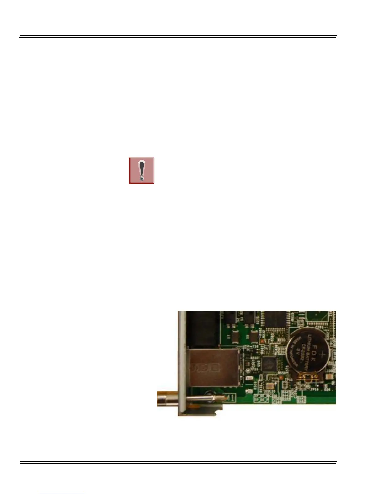
1. Install the battery on the GCD-CP10. The polarity “+” symbol
must be on top as illustrated in Figure 4-5 GCD-CP10 Battery
Installation.
Figure 4-5 GCD-CP10 Battery Installation
The chassis power must be off when installing or
removing the GCD-CP10.
After removing a previously installed
GCD-CP10, handle the blade, carefully, from the
edges. If certain solder points/resistors are
touched on the back of the blade, some RAM/
temporary memory may be lost (e.g., time, date,
user-defined settings, etc.)
IMPORTANT INSTALLATION NOTES

 Loading...


