Home
NEC
Telephone
Univerge SV9100
Hardware Manual
Page 357
NEC Univerge SV9100 - Page 357
478 pages
Manual
To Next Page
To Next Page
To Previous Page
To Previous Page
Loading...
UNIVERGE SV9100
Issue 1.2
System Hardware Manual
5 - 97
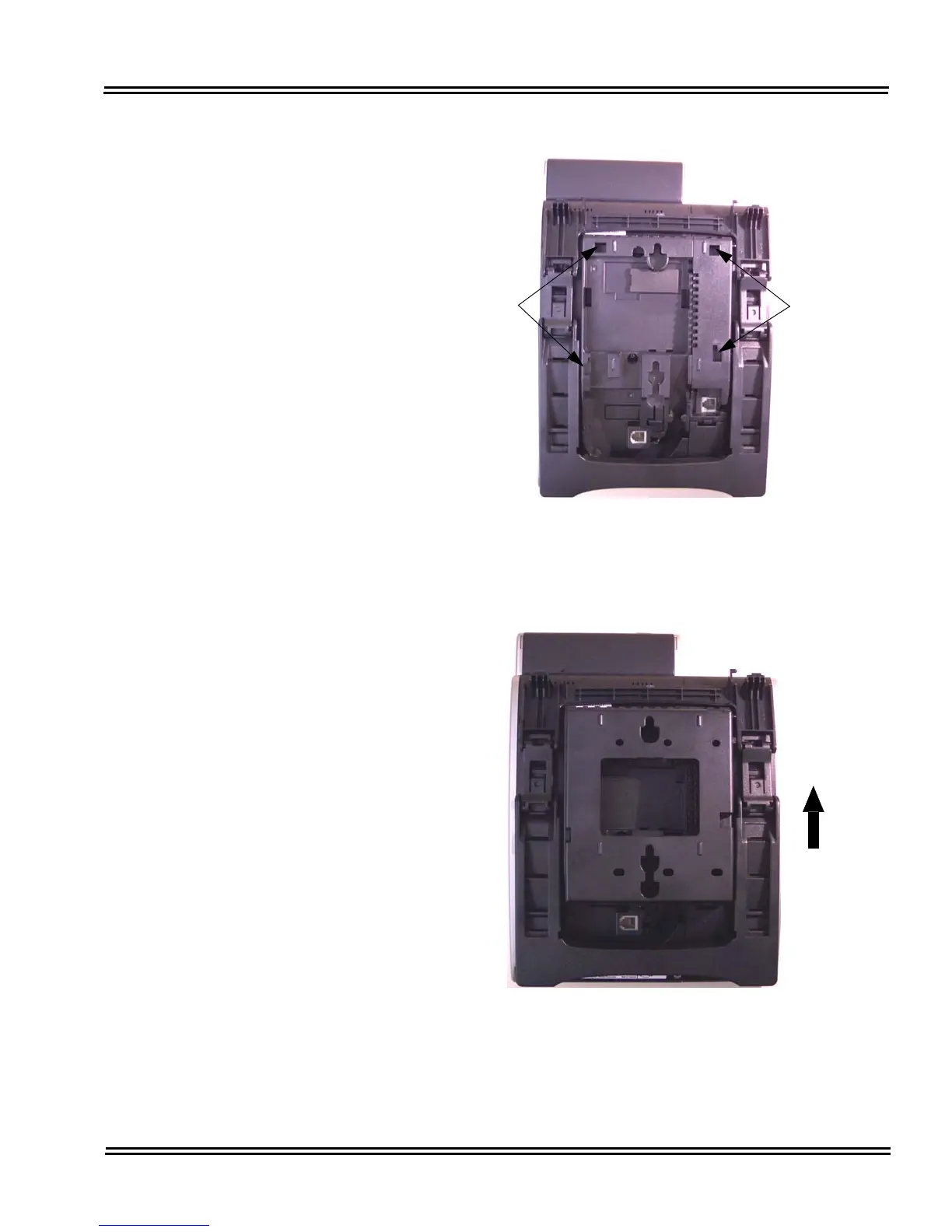
5.
Push up on the WM-L UNIT until it snap
s into place (refer to
Figure 5-105 WM-L UNIT I
nstalled
).
Figure 5-104 Cutouts for
WM-L UNIT
Figure 5-105 WM-L UNIT Inst
alled
Cutouts
Cutout
s
356
358
Table of Contents
Main Page
Default Chapter
3
Table of Contents
3
Issue
20
Regulatory
21
Chapter 2 SV9100 System Specifications
25
Chapter 1 Introduction to SV9100
25
General Information
25
Section 1 General Information
25
Section 2 Equipment List
29
System Block Diagram
41
Maximum System Capacities
45
System Configuration - SV9100
46
Cabling
57
Power Requirements
60
Power Supply Specifications
60
Power Supply Consumption
61
Environmental Conditions
62
Temperature and Humidity
62
Outside Line Types
63
Transmission, Network, and Control Specifications
63
Transmission
63
Network
63
Control
63
Dialing Specifications
64
Dial Pulse Address Signaling
64
Dual-Tone Multifrequency (DTMF) Address Signaling
64
External Equipment Connection
65
External Paging (Audio)
65
External Tone Ringer/Night Chime Output
65
Music Source for Music on Hold Via Chassis
65
Music Source for Station Background Music Via ACI
65
PC Connection
66
Relay Contact
66
SMDR Output
66
Battery Backup
66
Memory Backup
66
System Backup (Optional)
66
Weights and Dimensions
67
Chapter 3 Installing the SV9100 Chassis
73
Section 1 General Information
73
Installing the 19" (CHS2UG) Chassis
73
Installing the 19" Controlling Chassis
74
Installing Expansion Blades in the 19" Chassis (Optional)
75
Connector Pin-Out on the GPZ-BS10/GPZ-BS11
77
Install the GPZ-BS10 Expansion Base Blade in the CHS2UG Controlling Chassis
77
Install the GPZ-BS11 Expansion Blade in the CHS2UG Expansion Chassis
80
Connect the Controlling and Expansion Chassis
83
Install Grounding on 19" Chassis
85
Install Grounding on Multiple 19" Chassis (Optional)
86
Install AC Power Cords on 19" Chassis
87
Apply Power to the 19" Chassis
88
Install AC Power Cords on Multiple 19" Chassis (Optional)
88
Install Additional Blades 19" Chassis
88
Installing the 9.5" Base (CHS2UG) Chassis
88
Install Grounding on 9.5" Chassis
89
Apply Power to the 9.5" Gateway or Base Chassis
90
Install AC Power Cord 9.5" Gateway or Base Chassis
90
Install Additional Blades 9.5" Gateway or Base Chassis
90
Installing the 9.5" Chassis
90
Wall Mounting the Chassis
90
Wall Mounting the 19" (CHS2UG) Chassis
90
CHS2UG Chassis Wall Mount Installation
90
Wall Mounting the 9.5" Chassis
97
Option 1 - Wall Mounting the 9.5 Inch (CHS2UG) Chassis
97
Wall Mounting the 9.5 Inch (CHS2UG) Chassis
99
Wall Mounting the CHS2UG Without the CHS2UG B Small Batt Box
101
Floor Mounting the Chassis
108
Floor Mounting the 19" (CHS2UG) Chassis
108
CHS2UG Chassis Installation
108
Multiple CHS2UG Chassis Installation
111
Stand Mounting the 19" (CHS2UG) Chassis
113
CHS2UG Chassis Installation
113
Multiple CHS2UG Chassis Installation
115
Stand Mounting the 9.5" CHS2UG B Chassis
118
Rack Mounting the Chassis
122
Rack Mounting the 19" (CHS2UG) Chassis
122
Battery Connection
125
Installing the Internal Batteries 19" (CHS2UG) Chassis
125
Installing the External Batteries 19" (CHS2UG) Chassis
130
Floor Mounting the CHS LARGE BATT BOX
130
Battery Installation
132
CHS LARGE BATT BOX to CHS2UG Connection
136
CHS LARGE BATT BOX Fuse Replacement
139
Installing the CHSGW SMALL BATT BOX on the 9.5" Chassis
142
CHSGW SMALL BATT BOX Installation
142
CHSGW SMALL BATT BOX Fuse Replacement
148
Installing the External Batteries (CHS LARGE BATT BOX) to the 9.5" Gateway (CHS2U GW) or Base (CHS2UG) Chassis
149
CHS LARGE BATT BOX Installation
149
CHS LARGE BATT BOX to 9.5" Chassis Connection
150
CHS LARGE BATT BOX Fuse Replacement
151
Power Supply
151
Remove and Install Cooling Fan
151
CHS2UG Chassis
151
Remove Cooling Fan
152
Install Cooling Fan
153
Chapter 4 Installing the SV9100 Blades
155
Section 1 General Information
155
Slot Locations
155
Installation
157
Installation and Safety Precautions
157
Section 2 Installation
157
Installing an Extension or Trunk Blade
158
Installing the Blades
158
Order of Installing Extension Blades
159
Installing GCD-4COTA, GCD-4DIOPB, GCD-4ODTB or GCD-2BRIA Blades
160
Order of Installing Trunk Blades
160
Installing GCD-PRTA (T1/PRI) Blades
162
Remove an Extension or Trunk Blade
162
Uninstalling a Blade Slot through Software
162
Blade Capacities
163
Powering up the SV9100
163
Performing a Cold Start
163
Initial Programming
164
Performing a Hot Start
164
Resetting the System
164
Port Defaults
165
Setting up Extension Circuit Types
165
Backing Up/Restoring a Database
166
Saving Your Configuration
166
Performing a Software Upgrade
167
Common Control Blades
169
GCD-CP10 (SV9100 Central Processing Unit)
170
Description
171
Installation
174
Background Music (BGM) or Music on Hold (MOH)
176
GPZ-IPLE Daughter Board Installation
176
SD-A1 US/SD-B1 US Installation
176
Switch Settings
177
LED Indications
177
Connectors
179
GPZ-IPLE (Voice over IP Daughter Board)
181
Description
181
Installation
182
Switch Settings
182
LED Indications
182
Connectors
184
Station Blades
186
GCD-8DLCA/GCD-16DLCA (Digital Station Interface)
186
Description
186
Installation
187
LED Indications
187
Connectors
188
GPZ-8DLCB (Digital Station Daughter Board)
190
Description
190
Installation
192
GPZ-8DLCB Daughter Board Cable Connection
192
GCD-4LCA/ GCD-8LCA (4-Port/8-Port Single Line Interface)
194
Description
194
Installation
196
LED Indications
196
Connectors
198
GPZ-4LCA/GPZ-8LCE (4-Port/8-Port SLI Daughter Boards)
198
Description
200
Installation
201
Connectors
202
GCD-LTA (D Term /SLT Combination)
203
Description
203
Installation
204
LED Indications
205
Connectors
206
Trunk Blades
207
GCD-4COTA (4 Loop Start Interface)
208
Description
208
Installation
209
LED Indications
209
Connectors
210
GPZ-4COTE (4 Loop Start Interface Daughter Board)
211
Description
211
Installation
213
Connectors
213
GCD-2BRIA (2 Basic Rate Interface)
215
Description
215
Installation
216
LED Indications
217
Connectors
218
Termination Switch Settings
218
PZ-2BRIA (2 Basic Rate Interface Daughter Board)
220
Description
221
Installation
221
Connectors
222
Termination Switch Settings
223
GCD-4DIOPB (DID/OPX Interface)
224
Description
224
Installation
225
LED Indications
225
Connectors
226
GCD-PRTA (PRI Interface)
227
Description
227
Installation
228
LED Indications
230
Connectors
232
GCD-4ODTB (4-Port Tie Line Interface Blade)
234
Description
234
Installation
235
LED Indications
236
Connectors
236
Connections
238
CD-VM00 (Voice Mail and Server)
240
Description
240
Installation
241
LED Indications
242
Active LED - Green
242
Application LED - Red/Green (Dual Color)
243
Busy LED - Red
243
Compactflash Card Activity LED - Red
243
Connectors
243
RS-232 Interface
243
DB9 to 6-Pin Modular RS-232 Adapter
244
Serial Cable (DTE)
244
10 Base-T/100 Base-TX Ethernet Interface
245
Serial Cable (DCE)
245
USB Interface
245
VGA Display Interface
245
CD-PVAA (Packet Voice Application)
247
Description
247
Installation
248
Switch Settings
248
LED Indications
248
Connectors
249
GCD-RGA (Application Gateway)
250
Description
250
Installation
252
Switch Settings
252
Status Leds
253
LED Indications
253
Connectors
254
CD-ETIA (Gigabit Poe Switch)
255
Description
255
Installation
256
Stacking Architecture
256
GCD-CP10IP Address Assignment
257
Group Formation
257
Port Number Determination
257
Unmanaged Switch Functions
258
LED Indications
258
Connectors
258
Chapter 5 Installing DT Series Digital and IP Multiline Terminals
265
Dtl-2E-1 (Bk) Tel
265
Dtl-6De-1 (Bk) Tel
275
Dtl-8Ld-1 (Bk) Tel/Dtl-8Ld-1 (Wh) Tel
276
Dtl-12Bt-1 (Bk) Tel
277
Dtl-12D-1 (Bk) Tel/Dtl-12D-1 (Wh) Tel
278
Dtl-12Pa-1 (Bk) Tel
279
Dtl-24D-1 (Bk) Tel/Dtl-24D-1 (Wh) Tel
280
Dtl-32D-1 (Bk) Tel/Dtl-32D-1 (Wh) Tel
281
DT400 Series Digital Multiline Terminals
282
Dtz-2E-3 (Bk) Tel
282
Dtz-6De-3 (Bk) Tel
283
Dtz-12D-3 (Bk)/(Wh) Tel
284
Dtz-24D-3 (Bk)/(Wh) Tel
285
Dtz-8Ld-3 (Bk)/(Wh) Tel
286
DT700 IP Multilineterminals
287
Itl-2E-1 (Bk) Tel
287
Itl-6De-1 (Bk) Tel
288
Itl-8Lde-1 (Bk) Tel
289
Itl-8Ld-1 (Bk) Tel/Itl-8Ld-1 (Wh) Tel
290
Itl-12D-1 (Bk) Tel/Itl-12D-1 (Wh) Tel
291
Itl-12Cg-3 (Bk) Tel
292
Itl-12Dg-3 (Bk) Tel
293
Itl-12Pa-1 (Bk) Tel
294
Itl-24D-1 (Bk) Tel/Itl-24D-1 (Wh) Tel
295
Itl-32D-1 (Bk) Tel/Itl-32D-1 (Wh) Tel
296
Itl-320C-1 (Bk) Tel
297
DT800 Series IP Multiline Terminals
298
Itz-12D-3 (Bk)/(Wh) Tel
298
Itz-12Cg-3 (Bk)/(Wh) Tel
299
Itz-12Dg-3 (Bk)/(Wh) Tel
300
Itz-24D-3 (Bk)/(Wh) Tel
301
Itz-8Ldg-3 (Bk)/(Wh) Tel
302
Install Multiline Terminals
303
Connecting the DT300/DT400 Series Multiline Terminal to the System
303
Connecting the Handset
303
Handset Connection DT300
303
Handset Connection DT400
303
Connecting the Line Cord
304
Line Cord Connection DT300
304
Line Cord Connection DT400
305
Applying Power to the DT700 Multiline Terminals
307
Connecting the DT700/DT800 Series IP Multiline Terminal to the Network and PC
308
Section 3 DT700/DT800 Series IP Multiline Terminals
308
Adjusting the LCD on the Multiline Terminal
309
Installing Line Key Kit (12LK-L KIT)
310
Installing the 12LK-L KIT
310
Configuring the Digital Telephone for the Correct Number of Line Keys
314
Configuring the IP Telephone for the Correct Number of Line Keys
314
Installing the Directory Card on the Multiline Terminal
316
Installing a Numbered Keypad on the Multiline Terminal
317
Installing the Numbered Keypad on a Multiline Terminal
319
Configuring the Digital Telephone for the Numbered Keypad
321
Configuring the IP Telephone for the Numbered Keypad
321
Adjusting the Height on the Multiline Terminal
323
Install the BS (Braille)-L (BK) KIT
324
Adjusting the Height on the Multiline Terminal
326
Removing or Installing the Tilt Legs on the Multiline Terminal
326
Remove Tilt Legs
326
Install Tilt Legs
327
Wall Mounting the Multiline Terminal
330
Wall Mounting a Multiline Terminal Using the Base Plate
330
Adjusting the Hanger Hook
330
Wall Mounting the Multiline Terminal
331
Removing the Multiline Terminal from the Wall Mounted Base Plate
332
Wall Mounting the Base on a Switch Box
333
DT Series Terminal Options
334
DT Series Optional Terminal Equipment
336
8Lk-L (Bk) Unit/8Lk-L (Wh) Unit
336
Installing the 8LK-L UNIT
336
8Lkd (Ld)-L (Bk) Unit/8Lkd (Ld)-L (Wh) Unit
338
Installing the 8LKD (LD)-L UNIT
339
8Lki (Ld)-L (Bk) Unit/8Lki (Ld)-L (Wh) Unit
342
Installing the 8LKI (LD)-L UNIT
343
Dcl-60-1/Dcz-60-2 Console (Bk/Wh)
346
Installing the DCL-60-1/DCZ-60-2 CONSOLE
347
Lcd (Bl)-L (Bk) Unit/Lcd (Bl)-L (Wh) Unit
351
Lcd (Bl)-Z Unit (Bk/Wh)
352
Panel( )-L Unit
352
WM-L UNIT Attached to Wall
353
Release the WM-L UNIT
355
WM-L UNIT Attached to Wall Plate
356
Removing the Multiline Terminal from the Wall Mounted Plate
358
Dss Wm-L Unit
359
Mount DCL-60-1/DCZ-60-2 CONSOLE on Wall Using DSS
359
Mount DCL-60-1/DCZ-60-2 CONSOLE on Wall Plate Using DSS WM-L UNIT
360
Optional Handsets
362
ITL / DTL PTM Handset
362
ITL / DTL PTT Handset
362
UTR-1-1 USB Handset
363
Handset Connection
363
USB Connection
363
Wall Mounting
364
Section 7 Bluetooth Cordless Handset
365
Selecting a Location
366
Controls and Indicators
367
Installing the Bluetooth Cordless Handset
369
Wall Mounting the Bluetooth Cradle
375
Remove and Replace Handset Battery
378
Bluetooth Hub Adapter (BHA) Features
379
Installing the BHA-L UNIT
379
Pairing a Bluetooth Device and Multiline Terminal (Bluetooth Installed)
381
Accessing the Bluetooth Device Setup Screen
381
Entering a PIN Code
381
Pairing
381
Connecting the Paired Device
382
Unpairing
382
Visibility Setting
382
BT Information
383
Installing the SLT Adapter
384
Section 9 Single Line Telephone
384
Wall-Mounting the SLT Adapter
385
Cordless DECT (DTL-8R-1)
387
Specifications
388
Battery Safety
389
Important Safety Instructions
390
Important Electrical Considerations
391
Connecting the Telephone Cords
394
Installation Precautions
394
Selecting a Location
394
Applying Power to the Charging Unit
396
Mounting the Base to a Standard Wall Plate
397
10.10 Mounting the Base Directly to the Wall
400
10.11 Wall Mounting the Charging Unit
402
10.12 Attaching and Removing the Belt Clip
403
10.13 Installing the Handset Battery Pack
404
10.14 Charging Batteries
405
10.15 Charging Spare Battery Packs
405
Section 11 ML440/AP300 Cordless Handset
406
Connecting the Base Station
406
Install the Base Station
406
Base Station Wall Mounting Installation
408
Handset and Charger
409
Charging the Battery
410
Powering on the Handset
411
Chapter 6 Installing SV9100 Optional Equipment
413
General Information
413
Pgd(2)-U10 Adp
413
Using a PGD(2)-U10 ADP
413
LED Indications
414
Setting up PGD(2)-U10 ADP Connections
414
Background Music
422
Installing Background Music
422
Section 3 Background Music
422
Installing a Door Box
423
Section 4 Door Box
423
External Paging
427
External Page
427
Installing an External
427
Section 5 External Paging
427
External Paging and Door Box
429
External
429
Door Box /External Page Relay Contacts
430
Connecting a Contact Relay Device to a Door Box/External Page
430
Relay
430
External Recording System or External Ringer
431
Installing an External Recording System or External Ringer
432
Programming
433
Music Sources
436
Music on Hold
436
Installing External Music on Hold
436
Section 8 Music Sources
436
Night Mode Selection
439
Night Mode Selector Switch
439
Connecting a Night Mode Selector Switch
439
Section 10 Telephone Labeling
439
DESI Printer Sheets
439
Removing the Faceplate
440
Replacing the Faceplate
440
Section 11 Telephone Adapters
441
Using Adapters
441
In-Line Power Adapter (ILPA-R)
441
Conditions
442
Installation
443
Ada-L Unit
445
ADA-L UNIT Switch Settings
446
Installing the ADA-L UNIT
447
ADA-L UNIT Connection
449
ADA-L UNIT Connection for Recording Only
449
ADA-L UNIT Connection for Sending Recorded Calls to the Telephone
450
Apr-L Unit
450
APR-L UNIT Switch Settings
451
Installing the APR-L UNIT
452
Psa-L (Bk) Unit / Psa-L (Wh) Unit
455
Installing the PSA-L Adapter
456
Using the PSA-L Adapter
462
Gigabit Adapter (GBA-L UNIT)
463
Installing the GBA-L UNIT
464
GBA-L UNIT Connection
472
LED Display
472
Section 12 Power Failure Telephones
473
Power Failure
473
Connector Pin-Outs on COIU Blade for Power Failure Circuits
474
Other manuals for NEC Univerge SV9100
Manual
766 pages
Programming Manual
954 pages
Features And Specifications
1402 pages
Quick Reference Guide
15 pages
User Guide
186 pages
System Hardware Manual
740 pages
Installation Manual
136 pages
Configuration Guide
37 pages
General Description Manual
190 pages
Reference Guide
5 pages
System Maintenance Manual
105 pages
Related product manuals
NEC UNIVERGE SV9100 DT750
122 pages
NEC SoundTel NEC Univerge SV9100
8 pages
NEC UNIVERGE SV9300 DT410
100 pages
NEC Univerge SV 9500
263 pages
NEC Univerge SV8100 DT310
78 pages
NEC UNIVERGE DT310
216 pages
NEC UNIVERGE DTK-12D-1
94 pages
NEC UNIVERGE ITK-12D-1
94 pages
NEC UNIVERGE DTK-24D-1
94 pages
NEC UNIVERGE DTK-24D-1P
94 pages
NEC UNIVERGE DTK-12D-1P
94 pages
NEC UNIVERGE DT300 Series
41 pages

 Loading...


