— 6-28 —
6.3.3.3. Input Timing
!
Caution : The following show the timing of accepting pulses. In addition to the
conditions shown below, the maximum rotational speed of the Motor
places restrictions. Set the input pulse frequency so that the Motor
does not exceed its maximum rotational speed.
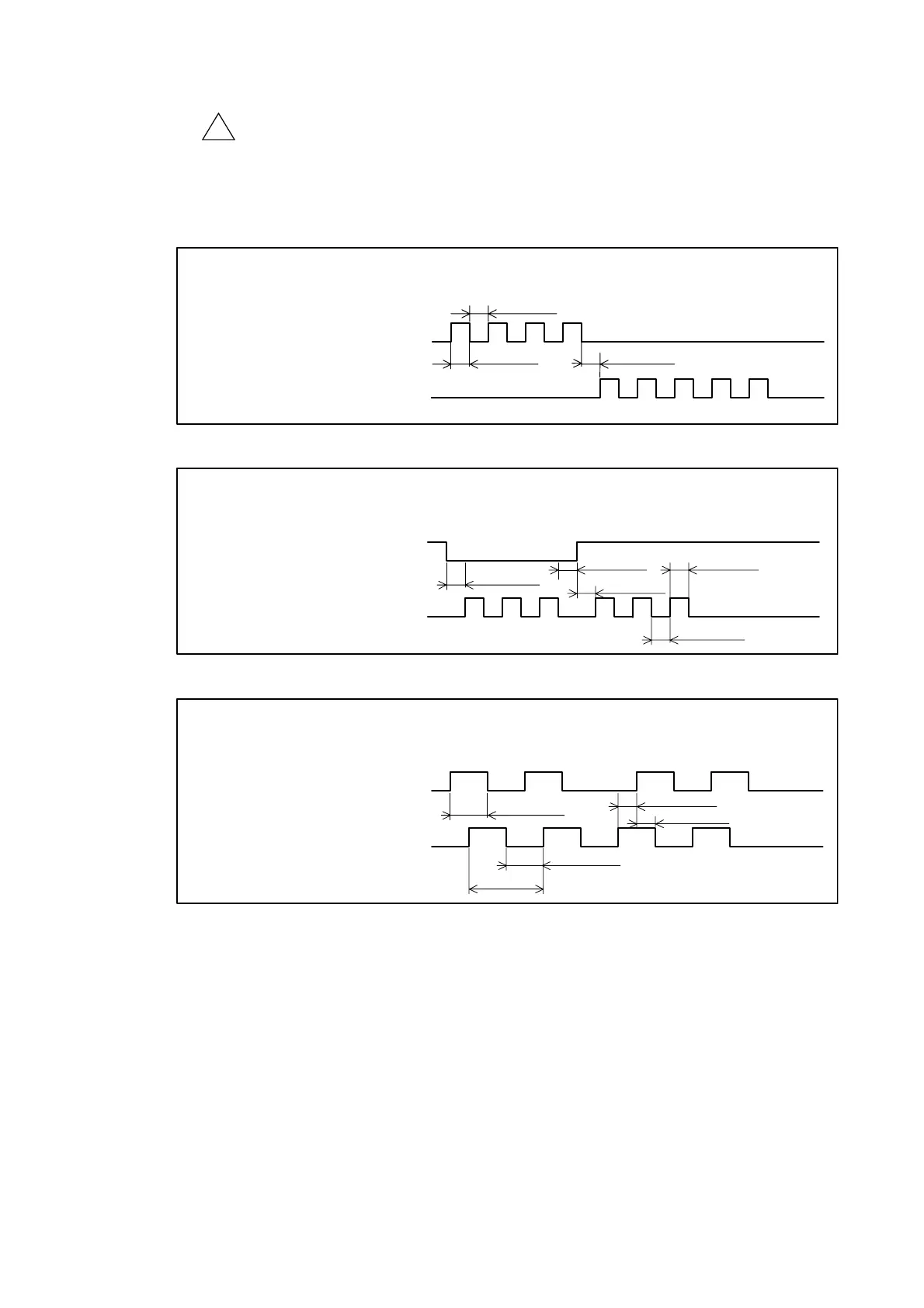
Fig 6-18: When the parameter is set to PC0 (CW/CCW format)
Min. 500 ns
CWP input port:
CW pulses
CCWP input port:
CCW pulses
ON
OFF
ON
OFF
Min. 500 ns
Min. 500 ns
Rotation in the minus direction Rotation in the plus direction
Fig 6-19: When the parameter is set to PC1 (Pulse and direction format)
Min. 500 ns
Min. 500 ns
CWP input: Direction
CCWP input: Step
ON
OFF
ON
OFF
Rotation in the minus directionRotation in the plus direction
Min. 500 ns.
Min. 500 ns
Min. 500 ns
Fig 6-20: When the parameter is set to PC4 (øA/øB format)
Min. 250 ns
Min. 1 µs
Min. 500 ns
CWP input: øA
CCWP input: øB
ON
OFF
ON
OFF
Rotation in the minus directionRotation in the plus direction
Min. 500 ns
Min. 250 ns

 Loading...


