— 2-29 —
2.10. CN3: Resolver Cable Connector
!
Caution : Connect the Cable Set provided with the Driver Unit. Do not cut or
hookup to other cable because the Cable Set is uniquely made for the
position sensor.
Table 2-20: Connector list
Driver Unit connector
Molex Inc. 52986-1479 or equivalent
Mating connector type*
Molex Inc. 54306-1419* or equivalent
Mating connector shell type*
Molex Inc. 54331-0141* or equivalent
* Provided with the Cable Set.
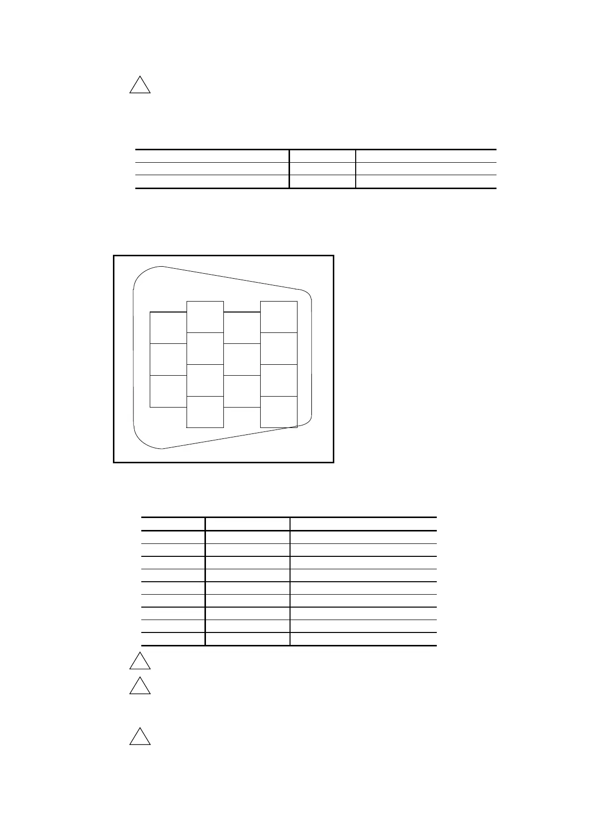
2.10.1. CN3 Pin-Out
Fig 2-30: Pin-out
1
INC-A
8
ABS-
COM
2
INC-B
9
INC-
COM
3
INC-C
10
–
4
–
11
–
5
ABS-A
12
–
6
ABS-B
13
–
7
ABS-C
14
FG
2.10.2. CN3 Signal List
Table 2-21: Signal list
Pin Signal name Function
1
INC-A Incremental resolve signal øA
2
INC-B Incremental resolver signal øB
3
INC-C Incremental resolver signal øC
5
ABS-A Absolute resolver signal øA+
6
ABS-B Absolute resolver signal øB+
7
ABS-C Absolute resolver signal øC+
8
ABC-COMMON Absolute resolver common
9
INC-COMMON Incremental resolver common
14
FG Frame ground
!
Danger : Never connect pins not listed above.
!
Danger : Check orientation of the connector when inserting it. Tighten the
screws to secure the connector so that it does not disconnect because
of shock or pulling.
!
Danger : Do not connect or disconnect the cable when the power of the Driver
Unit is on.

 Loading...


