— 3-9 —
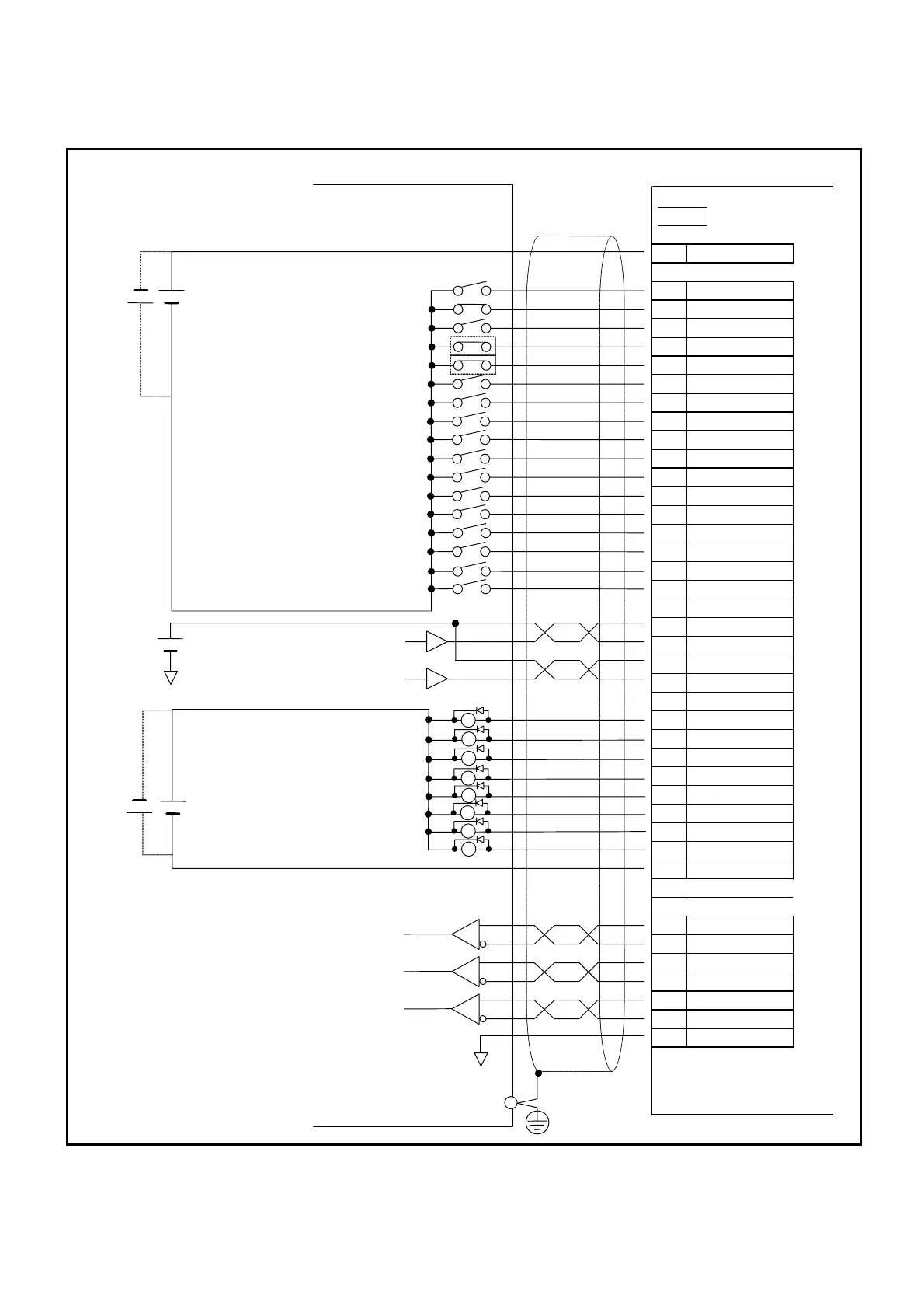
3.3.4.1. Wiring Example (CN2)
Fig 3-8: CN2 wiring example
Driver Unit ready
Warning
Over travel limit detection, + direction
Over travel limit detection, – direction
Servo ON state
State of operation
In position
Target proximity A
24 VDC
Polarity of the power supply may be
reversed to minus common.
Servo ON
Emergency stop
Alarm clear
Over travel limit, + direction
Over travel limit, – direction
Start positioning
Stop
Internal program channel selection 0
Internal program channel selection 1
Internal program channel selection 2
Internal program channel selection 3
Internal program channel selection 4
Internal program channel selection 5
Internal program channel selection 6
Internal program channel selection 7
Jog
Jog direction
User’s controller EDC Driver Unit
Position feedback signal øZ
Position feedback signal øB
Position feedback signal øA
5 VDC
CW pulse train
CCW pulse train
24 VDC
Signal ground
1,2 DC24
7 SVON
3 EMST
4
CLR
5 OTP
6 OTM
8 RUN
9 STP
11 PRG0
12 PRG1
13 PRG2
14 PRG3
15 PRG4
16 PRG5
17 PRG6
18 PRG7
19 JOG
20 DIR
22 CWP+
23 CWP–
24 CCWP+
25 CCWP–
28 DRDY
29 WRN
30 OTPA
31 OTMA
32 SVST
33 BUSY
34 IPOS
35 NEARA
26,27 COM
36 CHA
37 ¼CHA
38 CHB
39 ¼CHB
40 CHZ
41 ¼CHZ
43 SGND
CN2
FG
Polarity of the power supply may be
reversed to minus common.
 Loading...


