— A-1 —
Appendix 1: How to Monitor Input and Output Signal
The command IO monitors the state of Input and Output signals of CN2 connector.
This function is useful for checking the wirings.
Monitor for electric status: Monitor IO0
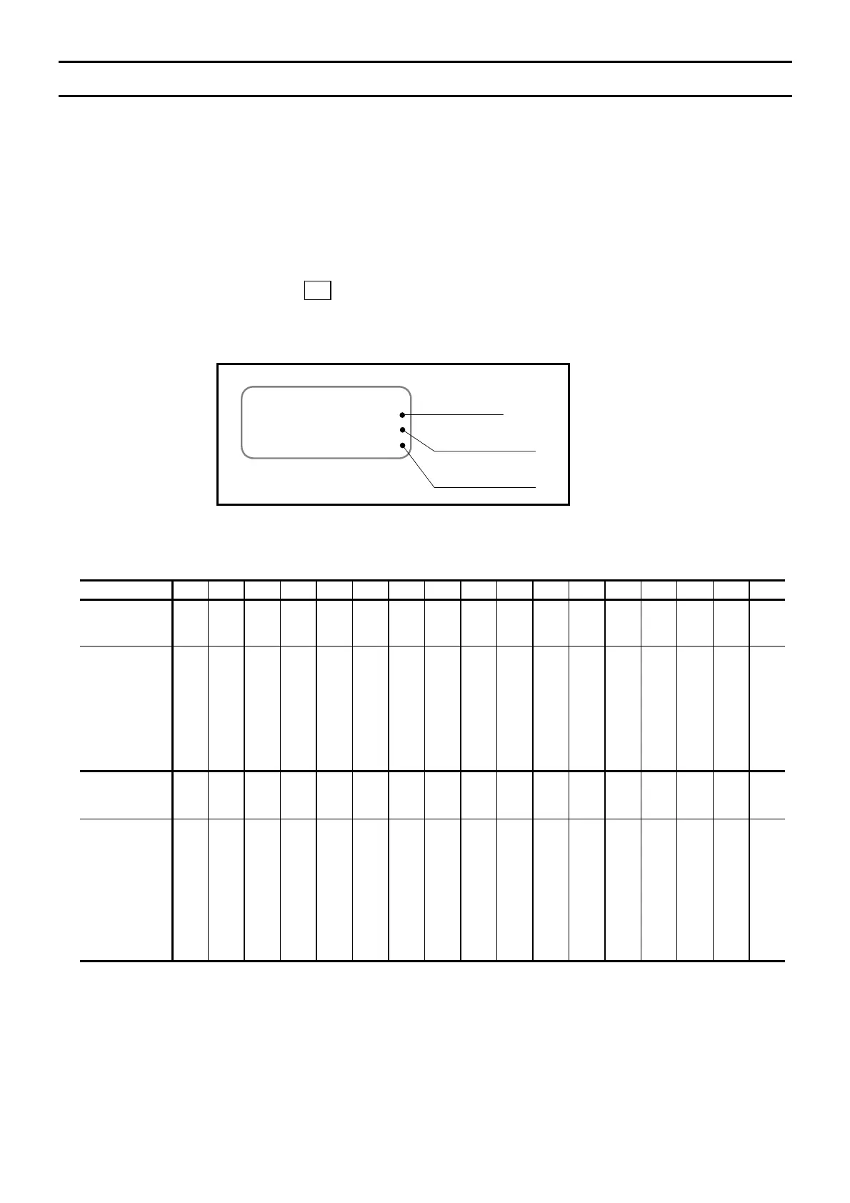
This monitor reports the electrical condition of the input and output ports.
◊ Input as “IO0/RP”.
Input the BS
key to terminate repetitive readout.
Fig A-1: Example of the monitor IO0
Input
IO0
GFEDCBA9876543210
00000000000000000
00000000000000000
I/O guide
Output
0: OFF
1: ON
0: Open
1: Closed
Table A-1: Monitoring contents of the monitors IO0 and IO1
Gide G F E D C B A 9 8 7 6 5 4 3 2 1 0
CN2
pin number
20 19 18 17 16 15 14 13 12 11 9 8 7 6 5 4 3
Pin code
(Shipping set)
PI16(DIR)
PI15(JOG)
PI14(PRG7)
PI13(PRG6)
PI12(PRG5)
PI11(PRG4)
PI10(PRG3)
PI09(PRG2)
PI08(PRG1)
PI07(PRG0)
PI06(STP)
PI05(RUN)
PI04(SVON)
PI03(OTM)
PI02(OTP)
PI01(ACLR)
PI00(EMST)
CN2
pin number
–
– – – – – – –
– 35 34 33 32 31 30 29 28
Pin code
(Shipping set)
Reserved
Reserved
Reserved
Reserved
Reserved
Reserved
Reserved
Reserved
Reserved
PO07(NEARA)
PO06(IPOS)
PO05(BUSY)
PO04(SVST)
PO03(OTMA)
PO02(OTPA)
PO01(WRN)
PO00(DRDY)

 Loading...


