— 7-26 —
7.3.1. Monitoring Way for Control Input/Output Signal
The monitor IO (Input/Output monitor) monitors the condition of inputs and outputs of the
connector CN2.
The monitor can be used for a wiring check.
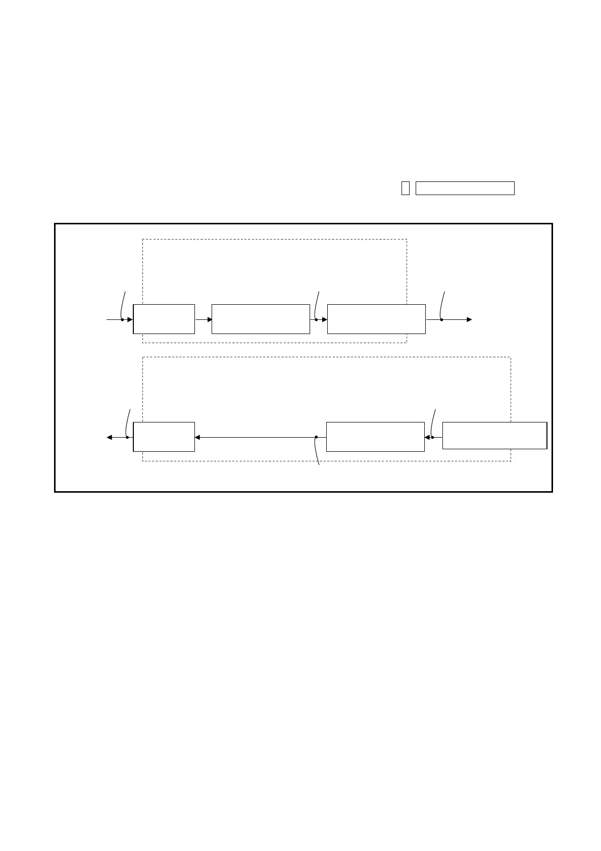
The relation between the monitor IO and the function of input and output of the Driver Unit is
illustrated in Figure 7-23 below. The IO1 to IO3 can monitor each part of inputs and outputs.
Another way to check availability of each function is to input F+Control I/O function.
Fig 7-23: Input/Output function and their condition monitor
Command PI: Edit input port (PI0 is set to the input EMST [Emergency stop].)
FN
:
Input function
AB
:
Input port polarity
NW: Anti-chattering timer
Input function
AB: Input port
0: normally open
1: normally closed
NW: Anti-chattering timer
0.0 to 1 000.0 (ms)
CN2 Input
FN: Input function
Function such as EMST and ACL
Monitor IO0 Monitor IO1
Monitor IO2
Monitor F
¼¼¼
(
¼
indicates function name.)
Command PO: Edit output port (PO0 is set to the output DRDY [Driver Unit ready] or the output NRM [normal]).
FN: Output function
GC: Output logic
ST: Stability timer
Output function
GC: Output logic
0: positive logic
1: minus logic
ST: Stability timer
0.0 to 1 000.0 (ms)
CN2: Output
FN: Output function
Function such as DRDY as WRN
Monitor IO0
Monitor IO1
Monitor IO3,
Monitor F
***
(
*
: function code)

 Loading...


