— 7-11 —
7.2.3. Over Travel Limit Direction: OTPA and OTMA
This output reports the entering direction of the Motor to the off-limits area specified by the
hardware over travel limits and the software over travel limits.
This output can be used to determine the direction to get out from the off-limits area.
Table 7-15: Signal logic of the OTPA (shipping set)
Table 7-16: Signal logic of the OTMA (shipping set)
Logic Description Logic Description
Open
Entered from the plus direction
Open
Entered from the minus direction.
Closed
Normal
Closed
Normal
The outputs of OTPA and OTMA are the negative logic. However, the logic can be changed to
the positive logic. Refer to “8.1.3.2. Editing Control Output” for the way to change the logic.
The System gets in the conditions shown in the table below when the output is activated.
Table 7-17: Indication of 7 segments LED when the output is activated.
7segments LED Command TA (Tell alarm status) Description
F2
F2>Software Over Travel
Software over travel
F3
F3>Hardware Over Travel
Hardware over travel
The direction, plus or minus, of the limit detected by the output OTPA or OTMA depends on the
setting of the parameter DI (Direction inversion) and the activated limit OTPA or OPMA as
described in the table below.
Table 7-18: Limit direction and outputs OTPA and OTMA
Activated limit (entering side)
Parameter DI
Activated
output
Hardware Software
OTPA OTP OTP
0
OTMA OTM OTM
OTPA
OTM
OTP
1
OTMA
OTP
OTM
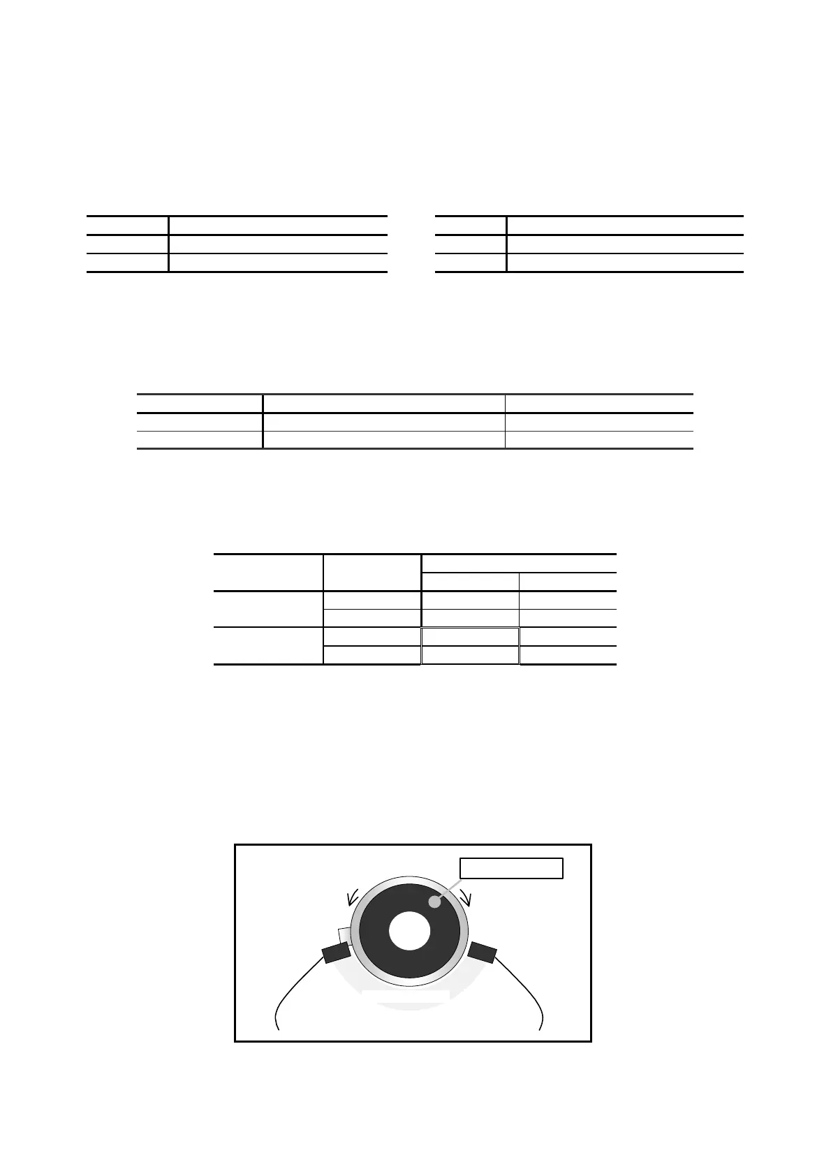
In particular, when the parameter DI is set to DI1, the relation between the hardware over travel and
the detected limit is unique. The unique relation between the counting direction of the position scale
and the travel limit switch is shown in the figure below.
◊ When the parameter DI is set to DI1, the Motor rotating in the plus direction enters the
off-limits area from the limit sensor OTM.
(This is because the plus direction of the Motor position scale is CCW.)
In this case, the output OTPA opens as the Motor enters in the off-limits area from the
plus side.
Fig 7-9: Over travel limit detraction when the parameter DI is set to DI1
Minus direction
To the input OTP To the input OTM
Motor output axis
Off-limits area
Plus direction

 Loading...


