— 7-2 —
7.1.2. Alarm Clear: ACLR
This input clears a warning.
Table 7-3: Signal logic of the input ACLR
Logic Description
↓ (ON ´ OFF)
Not effective
↑ (OFF ´ ON) Clears alarm.
A rising signal of the input ACLR from OFF to ON clears a warning while the output WRN
(Warning) is closed.
The state of the Motor servo returns to the same condition before the warning is occurred.
(Provided that no input, such as the input SVON, is given to change the state of servo.
The table below lists the warning that is given by the output WRN.
Table 7-4: Warning to be reported by the output WRN
‘7 segments LED
Command TA (Tell alarm status) Description Motor condition
A3 A3>Over Load Software thermal over Servo-off
A5 A3>Origin Undefined Home position undefined. No change
C0 C0>Pulse Command/Feedback Error
Error in the commanded
position or the feedback signal.
Servo-off
C5 C5>Fieldbus Warning
Warning of the field buss.
Cycle stop
F1
F1>Excess Position Error
Excessive position error
Servo-off
F5
F5>Program Error
Program error Cycle stop
F8 F8>AT Error Automatic tuning error Cycle stop
P5 P5>Main AC Line Under Voltage Low voltage of main power Servo-off
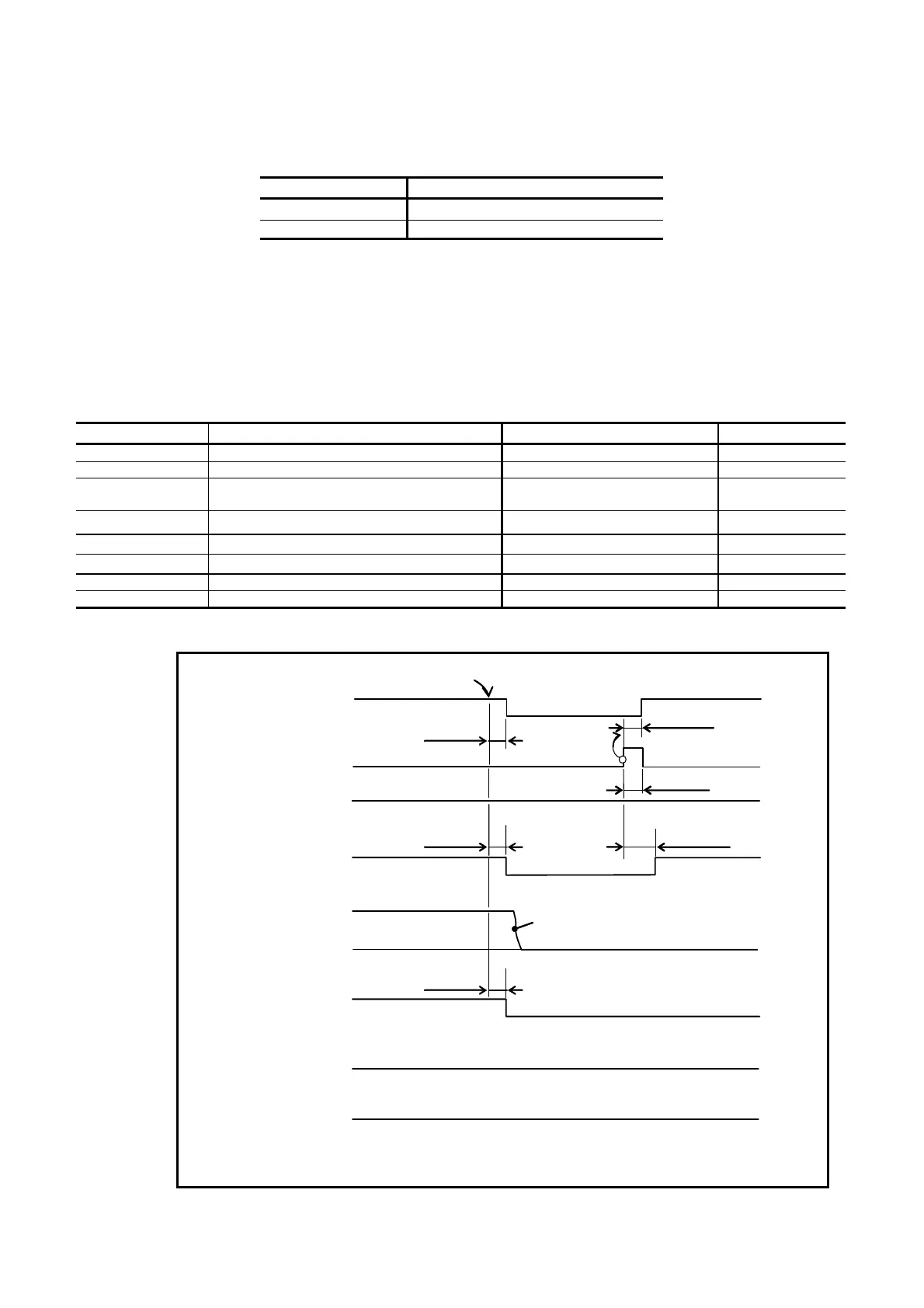
Fig 7-2: Signal timing of the input ACLR
Motor motion
closed
open
ON
OFF
Output WRN
Input ACLR
Output SVST
closed
open
closed
open
Output BUSY
closed
open
closed
open
Output IPOS
(FW
> 0: FIN)
Stops by the dynamic brake.
Input SVON
ON
OFF
Max. 1 ms
Max. 1 ms
Max. 1 ms.
Max. 1 ms
A warning occurs that makes the Motor servoe off.
Min. 1 ms
Output IPOS
(FW <
0: CFIN)
(FW =
0: IPOS)
Max. 170 ms (Max. 3.2 s)
¹
1
¹
1) It takes 3.2 seconds to activate the
Motor servo for the first time after
turning on the main power.

 Loading...


