— 8-1 —
8. More Advanced Function
8.1. Assignment of Input/Output Function
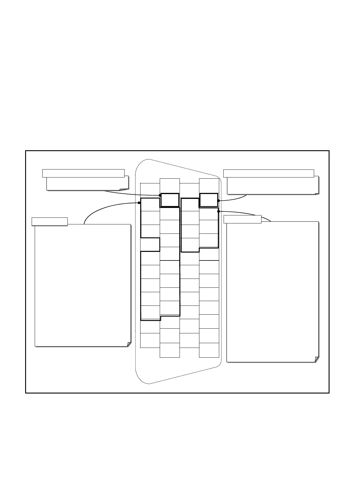
As shown in Figure 3-1 below, you can assign the function of inputs and outputs to each signal
port of the connector CN2 (Input/Output signal connector).
(Some ports are not available for function assignment.)
◊ Switching to extended functions.
◊ Setting the function that has been assigned to other port.
◊ Masking the function of the port that is not in use.
Thus, you may set the required functions to desired pin arrangement.
◊ You may change the port polarity of each port and insert a filter to individual ports.
Fig 8-1: Control input/output connector CN2 and assignable function to each port
1
DC24
26
COM
2
DC24
27
COM
3
PI0
(EMST)
28
PO0
(DRDY)
4
PI1
(ACLR)
29
PO1
(WRN)
5
PI2
(OTP)
30
PO2
(OTPA)
6
PI3
(OTM)
31
PO3
(OTMA)
7
PI4
(SVON)
32
PO4
(SVST)
8
PI5
(RUN)
33
PO5
(BUSY)
9
PI6
(STP)
34
PO6
(IPOS)
10
-
35
PO7
(NEARA)
11
PI7
(PRG0)
36
CHA
12
PI8
(PRG1)
37
*CHA
13
PI9
(PRG2)
38
CHB
14
PI10
(PRG3)
39
*CHB
15
PI11
(PRG4)
40
CHZ
16
PI12
(PRG5)
41
*CHZ
17
PI13
(PRG6)
42
-
18
PI14
(PRG7)
43
SGND
19
PI15
(JOG)
44
-
20
PI16
(DIR)
45
-
21
-
46
-
22
CWP+
47
-
23
CWP-
48
-
24
CCWP+
49
-
25
CCWP-
50
-
DRDY : Driver Unit ready
WRN : Warning
OTPA : Travel limit detection, + direction
OTMA : Travel limit detection, - direction
SVST : Servo state
BUSY : In-operation
IPOS : In-position
NEARA : Target proximity A
NEARB : Target proximity B
ZONEA : Zone A
ZONEB : Zone B
ZONEC : Zone C
TEU : Position error under
TEO : Position error over
TVU : Velocity under
TVO : Velocity over
TTU : Torque command under
TTO : Torque command over
TJU : Thermal loading under
TJO : Thermal loading over
OTXA : Travel limit ditection, ± direction
NRM : Normal
HOME : Home Return complete
HCMP : Home position defined
NONE : Mask function
DRDY : Driver Unit ready
NRM : Normal
EMST : Emergency stop
EMST : Emergency stop
ACLR : Alarm clear
OTP : Travel limit, + direction
OTM : Travel limit, – direction
SVON: Servo on
RUN : Positioning start
STP : Stop
PRG0: Internal program channel selection 0
PRG1: Internal program channel selection 1
PRG2: Internal program channel selection 2
PRG3: Internal program channel selection 3
PRG4: Internal program channel selection 4
PRG5: Internal program channel selection 5
PRG6: Internal program channel selection 6
PRG7: Internal program channel selection 7
JOG : Jogging
DIR : Jogging direction
HLD : Hold
ORD : Velocity override
IOFF : Integration off
HOS : Home Return start
HLS : Home position limit
NONE: (Set to a no-function port)
Input dedicated to safety function Output dedicated to safety function
General input
General out
ut
Note:1) Function in brackets is the shipping set
2) The pins with hyphen is prohibited.
The PI0 and PO0 are exclusive ports for the essential safety functions. There are some
restrictions on these ports as follow.
◊ You cannot change the function of the port PI0 (Pin No. 3: Input EMST). You can only
set the port polarity and the anti-chattering timer to it.
◊ You may change the function of the port PO0 (Pin No. 28: Output DRDY) to the
output NRM (Normal) only. You cannot set the output logic and stability timer to it.

 Loading...


