— 5-2 —
5.2. Tuning Level 1: Automatic Tuning
!
Caution : The automatic tuning does not function if the following conditions are
not met. Confirm them before carrying out the automatic tuning.
• The load moment of inertia must be in the allowable range of the Motor. Refer
to “3.2.1.4. Confirmation of Use Conditions.”
• The Motor is set horizontally. (The load condition of the Motor must not be
affected by external force such as the gravity.)
• Mechanical rigidity of the Motor mounting base and an attached load to the
Motor is sufficient enough.
• There must be no backlash or play caused by gears or couplings.
• Frictional load to the Motor shall be minimal.
If the above conditions are not met, proceed to “5.3. Tuning Level 2:
Servo Gain Tuning.”
Preparation
You need to prepare the following for the automatic tuning.
◊ Installation of the Motor. (Refer to “3.2.1.2. Motor Installation.”)
◊ Attach the load to the rotor of Motor. (Refer to “3.2.1.3. Coupling Load to Motor.”
◊ Installation of the Driver Unit. (Refer to “3.2.2. Installation of Driver Unit.”
◊ Connection of the Motor and the Driver Unit. (Use the cable set provided with the
Driver Unit.) Refer to “3.3.1.Connection of Cable Set.”
◊ Connection of the Handy Terminal.
◊ Connection to AC power source. Refer to “3.3.2. Connecting Power.”
◊ Wiring Servo ON (SVON) and Emergency stop (EMST) signal circuits.
(Connector CN2) Refer to “3.3.4. Connector Wiring.”
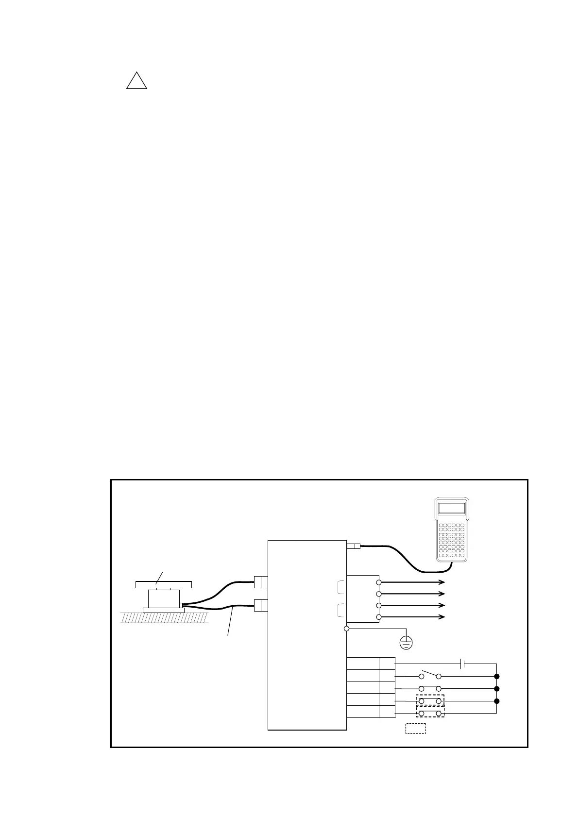
Fig 5-2: Wiring example of automatic tuning setup (reference only)
CN1
CN5
CN4
Contorl
power
CTRL
CN3
Main
power
MAIN
PE
DC24 1,2
SVON 7
CN2 EMST 3
OTP 5
OTM 6
Mounting base
Work or attachment
(Load inertia)
AC power
Handy Terminal
24 VDC
(External power supply)
Cable set
Motor
Over travel limit sensors
AC power
3
<
2
$
1
#
-
+
5
%
4
>
8
(
7
‘
6
&
.
=
0
?
9
)
CBA FED
IHG LKJ
ONM RQP
UTS XWV
?ZY */,
CTRLESCSHIFT ENTSPBS
NS
HANDY TERMINA L

 Loading...


