— 7-28 —
7.3.1.2. Monitor for Internal Recognition of Input and Output State: Monitor IO1
Monitors the applied state of following function to the control inputs and outputs:
◊ For the inputs, the monitor reports how the Driver Unit recognizes the application state
of functions.
(The readout is the applied state of parameters AB [Input polarity] and NW
[Anti-chattering timer] in the command PI [Edit input port])
◊ For the outputs, the monitor reports the state just before the application of output logic.
(The readout is the applied state of parameters ST [Stability timer]in the command PO
[Edit control output]. The parameter GC [Output logic] is not applied.)
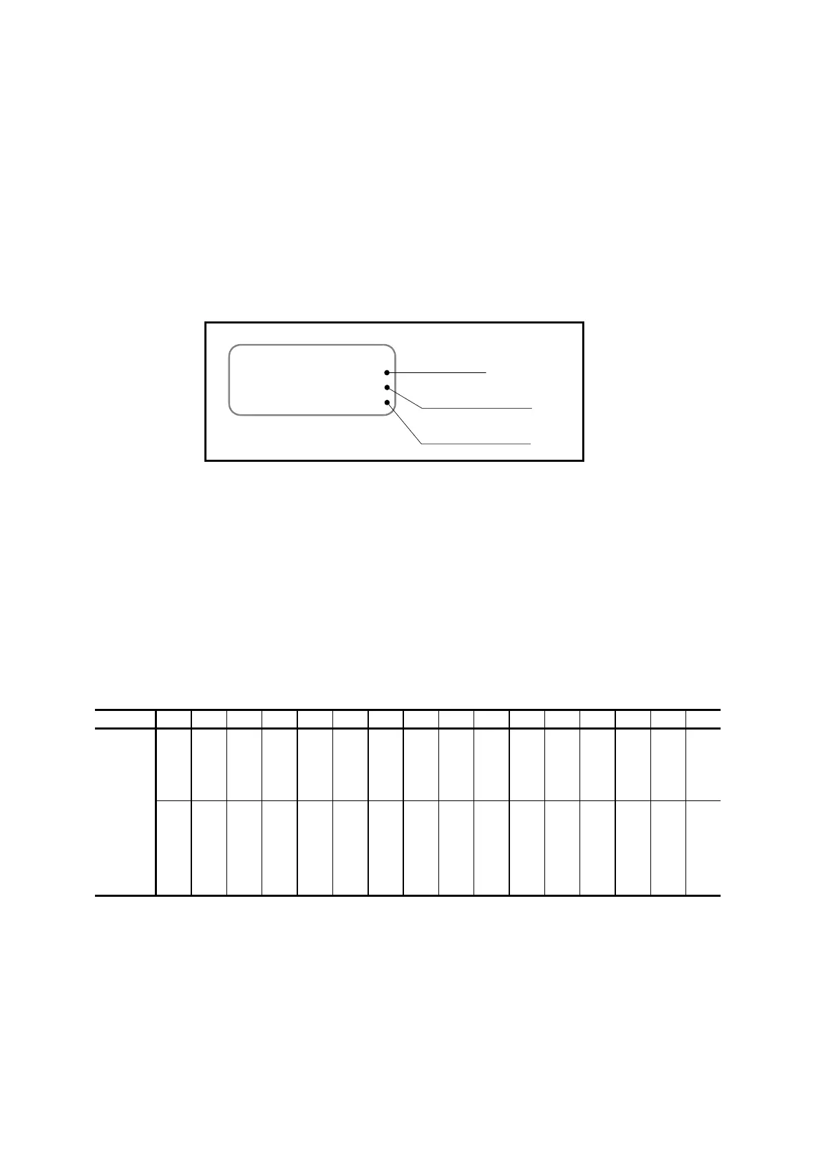
Fig 7-25: Example of Monitor IO1
IO1
GFEDCBA9876543210
00000000000000000
00000000000000000
State of input
Guide
State of output
0: Not functioning
1: Functioning
0: Not detected
1: Detected
7.3.1.3. Monitor for State of Input Functions: Monitor IO2
Monitors the application state of input functions in a line.
The readout is the recognition of the Driver Unit.
◊ The readout is the application state of the parameters AB (Input polarity) and NW
(Anti-chattering timer) in the command PI (Edit control input).
The code 1 denotes that the function is available and the code 2 denotes that the function is not
available.
Table 7-31: Readout of Monitor IO2
Guide F E D C B A 9 8 7 6 5 4 3 2 1 0
JOG
PRG7
PRG6
PRG5
PRG4
PRG3
PRG2
PRG1
PRG0
STP
RUN
SVON
OTM
OTP
ACLR
EMST
Function code
Reserved
Reserved
Reserved
Reserved
Reserved
Reserved
Reserved
Reserved
Reserved
Reserved
HLS
HOS
IOFF
ORD
HLD
DIR

 Loading...


