— 7-24 —
7.2.8.2. Signal Output Timing
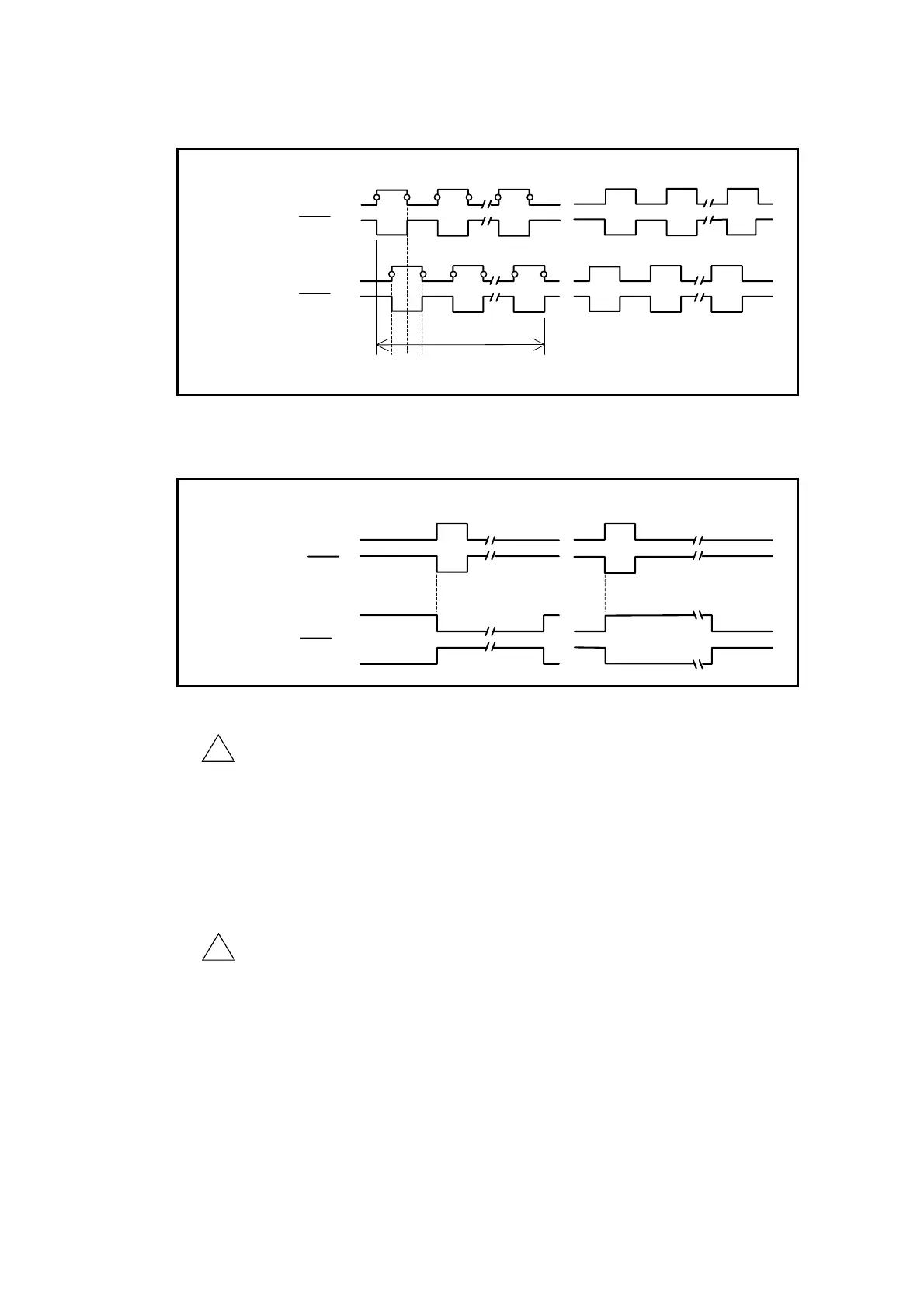
Fig 7-21: Signal timing of position feedback signal (øA/øB)
CHB output (øB)
¼
CHB output (øB)
CHA output (øA)
¼
CHA output (øA)
Rotation to CCW direction Rotation to CW direction
1 2 3 4 FR
・ ・ ・
One revolution
Fig 7-22: Signal timing of position feedback signal (øZ)
Rotation to CCW direction Rotation to CW direction
CHZ (output) (øZ)
¼
CHZ (output) (øZ)
CHZ output (MSB)
¼
CHZ output (MSB)
!
Caution : If the phase Z is used to specify the position scale of the Motor, be sure
to use the rising edge of the signal.
◊ The phase Z is made to have precise position repeatability on its
rising edge regardless of the Motor rotational direction.
◊ Use of the falling edge of the signal to detect the base position
won’t maintain the position repeatability because of the effect
caused by difference in pulse width when reversing the rotational
direction.
!
Caution : The output signals of the phases A, B and Z are not synchronized each
other.
 Loading...


