— 2-30 —
2.11. CN4: Motor Connector
!
Caution : Use the Cable Set provided with the Driver Unit. Please do not cut the
cable or hookup to other cable because the Cable Set is specially
made for the position sensor.
Table 2-22: Connector list
Connector of Driver Unit
WAGO Corporation 232-268 or equivalent
Mating connector
WAGO Corporation 231-638 or equivalent
* Provided with the Driver Unit.
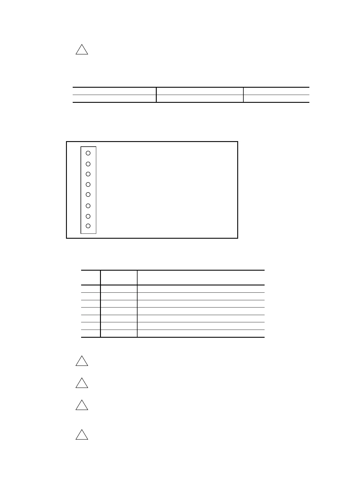
2.11.1. CN4 Pin-Out
Fig 2-31: Pin-out
U
V
W
R+
R-
SE+
SE-
Motor winding ø U
1
2
3
4
5
6
7
8
Motor winding ø V
Motor winding ø W
External dump resistor terminal
External dump resistor terminal
External dump resistor thermal sensor input*
External dump resistor thermal sensor
2.11.2. CN4 Signal List
Table 2-23: Signal list
Pin
No.
Signal
name
Function
1 U
Motor winding ø U
2 V
Motor winding ø V
3 W
Motor winding ø W
5 R+
External regeneration resistor terminal
6 R-
External regeneration resistor terminal
7 SE+
External regeneration resistor thermal sensor input*
8 SE-
External regeneration resistor thermal sensor input*
* Short these pins if external dump resistor is not in use. If they remain open, the alarm of
“over heat” occurs.)
!
Danger : Do not connect or disconnect the connector when the power of the
Driver Unit is on.
!
Danger : A high voltage is applied to the connector after the power is turned on.
Take extra care for short circuit.
!
Danger : Check the orientation of the connector when inserting it. Though the
connector is self-lock type, be sure to insert it to the bottom. Otherwise
you cannot secure the connector.
!
Danger : A high voltage remains between the pins R+ and R- even the main
power is turned off. Be careful not to get an electric shock.

 Loading...


