— 11-18 —
11.3.19. Over Travel F3: hardware Over Travel Limit
The followings are two types of setting of the off limits area to the Motor.
◊ Software over travel limit: The parameter sets the position data for the off limits area.
(Refer to “6.2.4. Software Over Travel Limit” for setting the off limits area.)
◊ Hardware over travel limit: Input signal from the limit sensors to the Driver Unit sets
the off limits area.
This warning reports that the Motor enters or passes through the off limits area set by the
software travel limits.
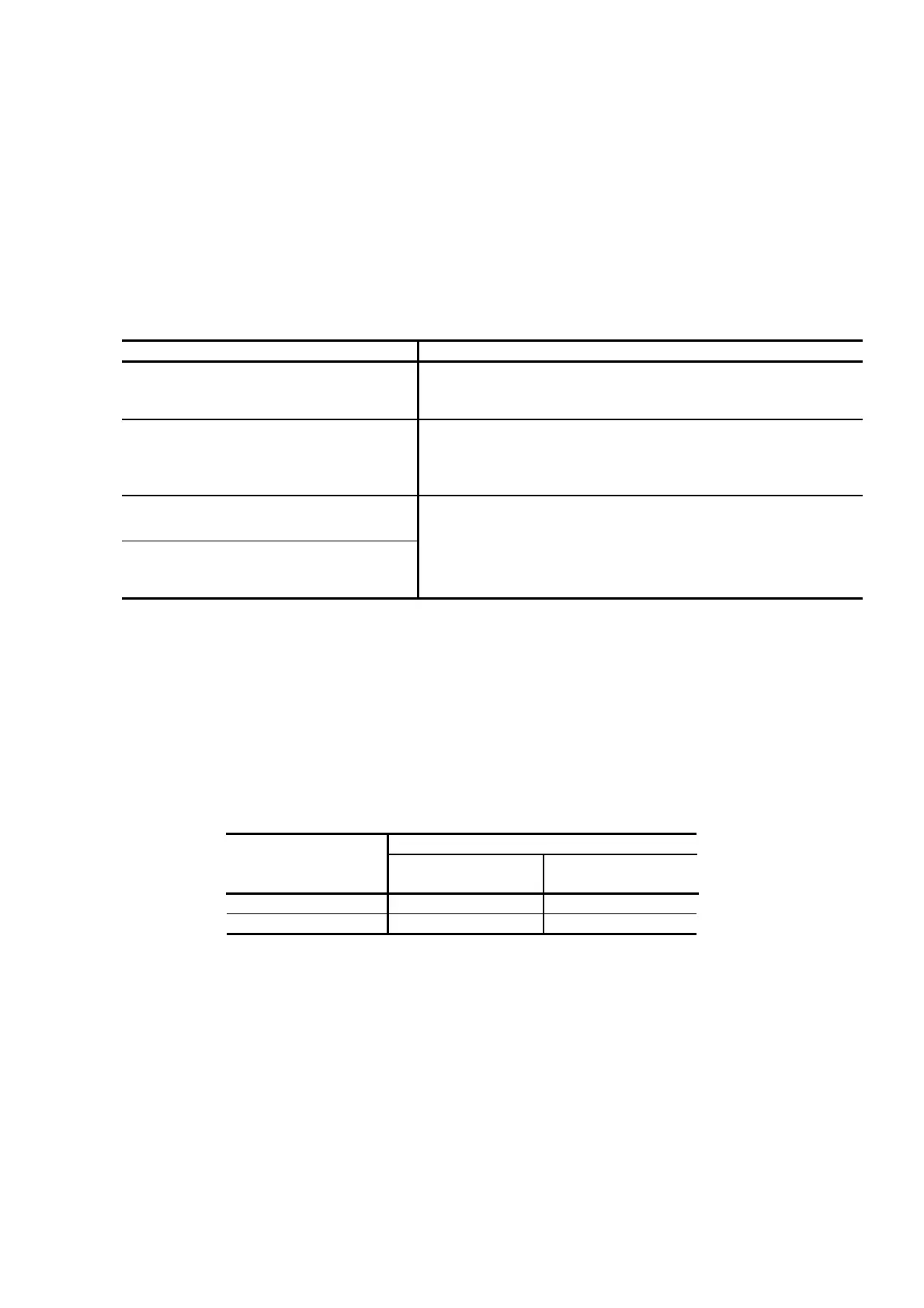
Table 11-27: Cause and Remedy for the over travel F3
Cause Remedy
(1)
Wrong polarity setting of OTP or
OTM input port.
• The shipping set of polarity of inputs OTP and OTM is normally
closed (Connector B).The warning occurs if the port is not
connected.
(2)
OTP or OTM is inputted.
• Input a command to move the Motor out of the off limits area as
the System accepts the move command to this direction.
• Turn off the Motor servo then move the Motor manually out of the
area.
(3)
Wrong wiring
(OTP ↔ OTM, etc.)
(4)
Defective limit sensor (Limit sensor
that is connected to OTPA or OTMA
sensors.)
• Check wiring of OTP and OTM.
• Check the OT sensor.
(1) When the limit sensor is activated, the state of over travel limit warning is purposely hold until
one of the following actions is taken. (Instantaneous over travel state holding function)
◊ Move the Motor opposite direction to the entered side
◊ Turn the Motor servo off and manually rotate the Motor opposite to the entered side.
(2) If the Motor gets in the software over travel limit area, the output of OTPA or OTMA will report
from which side the Motor entered into the area.
The plus or minus direction of the scale depends on the setting of parameter DI.
Table 11-28: Relation between OTPA and OTMA
Condition of Output OTPA and OTMA
Direction of intrusion
on the area
DI0
(Shipping set)
DI1
From OTP side
Output OTPA opens Output OTMA opens
From OTM side
Output OTMA opens Output OTPA opens
 Loading...


