— 2-21 —
2.9.1.1. CN2 Pin-Out
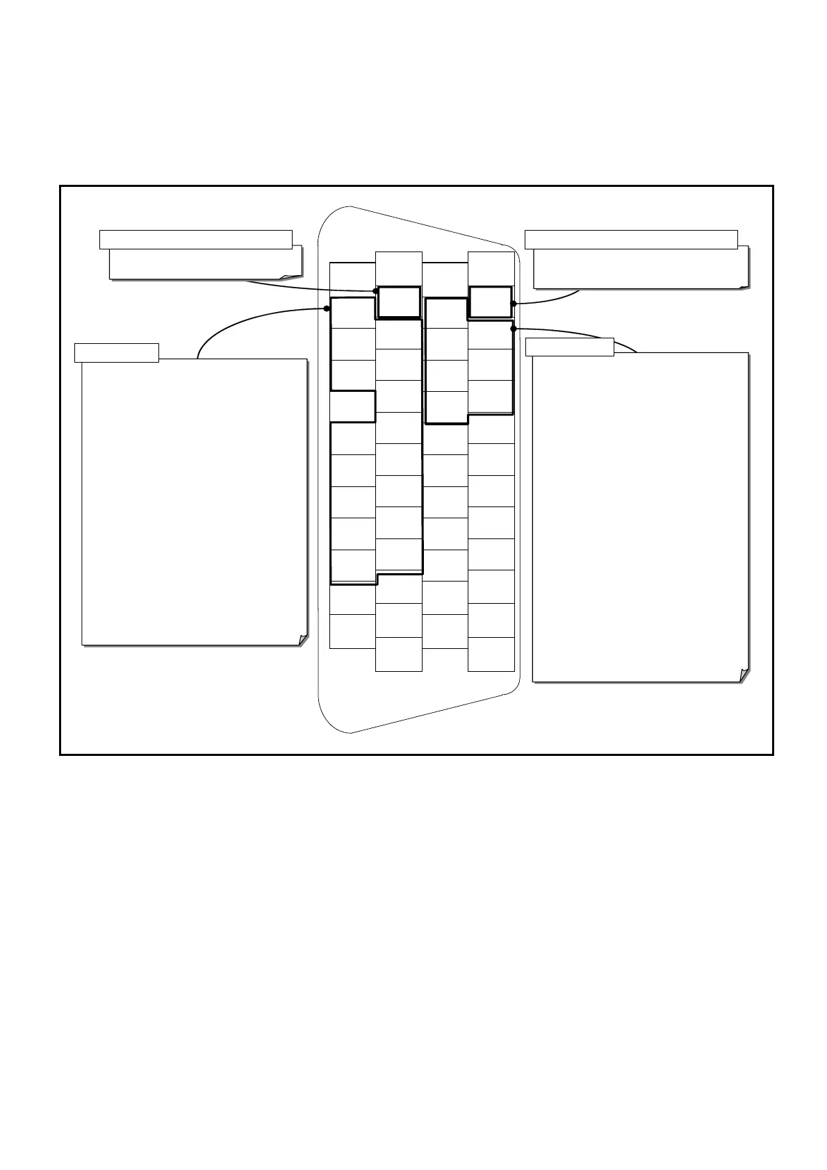
The pin-out arrangement below is for the shipping set. The function of each signal port may be
changed by the function setting of control Input/Output ports.
Fig 2-22: Pin-out (shipping set)
1
DC24
26
COM
2
DC24
27
COM
3
PI0
(EMST)
28
PO0
(DRDY)
4
PI1
(ACLR)
29
PO1
(WRN)
5
PI2
(OTP)
30
PO2
(OTPA)
6
PI3
(OTM)
31
PO3
(OTMA)
7
PI4
(SVON)
32
PO4
(SVST)
8
PI5
(RUN)
33
PO5
(BUSY)
9
PI6
(STP)
34
PO6
(IPOS)
10
-
35
PO7
(NEARA)
11
PI7
(PRG0)
36
CHA
12
PI8
(PRG1)
37
*CHA
13
PI9
(PRG2)
38
CHB
14
PI10
(PRG3)
39
*CHB
15
PI11
(PRG4)
40
CHZ
16
PI12
(PRG5)
41
*CHZ
17
PI13
(PRG6)
42
-
18
PI14
(PRG7)
43
SGND
19
PI15
(JOG)
44
-
20
PI16
(DIR)
45
-
21
-
46
-
22
CWP+
47
-
23
CWP-
48
-
24
CCWP+
49
-
25
CCWP-
50
-
DRDY : Driver Unit ready
WRN : Warning
OTPA : Travel limit detection, + direction
OTMA : Travel limit detection, - direction
SVST : Servo state
BUSY : In-operation
IPOS : In-position
NEARA : Target proximity A
NEARB : Target proximity B
ZONEA : Zone A
ZONEB : Zone B
ZONEC : Zone C
TEU : Position error under
TEO : Position error over
TVU : Velocity under
TVO : Velocity over
TTU : Torque command under
TTO : Torque command over
TJU : Thermal loading under
TJO : Thermal loading over
OTXA : Travel limit ditection, ± direction
NRM : Normal
HOME : Home Return complete
HCMP : Home position defined
NONE : Mask function
DRDY : Driver Unit ready
NRM : Normal
EMST : Emergency stop
EMST : Emergency stop
ACLR : Alarm clear
OTP : Travel limit, + direction
OTM : Travel limit, – direction
SVON: Servo on
RUN : Positioning start
STP : Stop
PRG0: Internal program channel selection 0
PRG1: Internal program channel selection 1
PRG2: Internal program channel selection 2
PRG3: Internal program channel selection 3
PRG4: Internal program channel selection 4
PRG5: Internal program channel selection 5
PRG6: Internal program channel selection 6
PRG7: Internal program channel selection 7
JOG : Jogging
DIR : Jogging direction
HLD : Hold
ORD : Velocity override
IOFF : Integration off
HOS : Home Return start
HLS : Home position limit
NONE: (Set to a no-function port)
Input dedicated to safety function Output dedicated to safety function
General input
General out
ut
Note:1) Function in brackets is the shipping set
2) The pins with hyphen is prohibited.
PI0 and PO0 are the dedicated ports to the safety function input and output respectively.
◊ You cannot change the function setting to the PI0 (Pin number 3: EMST input
[Emergency stop]). You may only set the logic of the connector and the stability timer
to it.
◊ You can only change the function of the PO0 (Pin number 28: DRDY output [Driver
Unit ready]) to the function NRM (normal) output. You cannot set the output logic and
the stability timer to it.
 Loading...


