— 7-35 —
7.4.1. Use of Preset Monitors
The following monitors are available by setting the parameter MN or MX with a suffixed
number from 0 to 8 to each parameter code.
Table 7-37: Preset analog monitor
Name (code) Function Data range Unit
MN0,MX0
Current velocity 0.000 to ±10.000
MN1,MX1
Commanded velocity 0.000 to ±10.000
s
-1
MN2,MX2
Velocity error 0.000 to ± 1.250 s
-1
MN3,MX3
Torque command 0.00 to± 100.00 %
MN4,MX4
øU current 0.00 to ±100.00 %
MN5,MX5
Transient position command 0.000 to ± 10.000 s
-1
MN6,MX6
0 to ± 127
MN7,MX7
Position error
0 to ± 16 383
pulse
MN8,MX8
Thermal loading 0.00 to 100.00
%
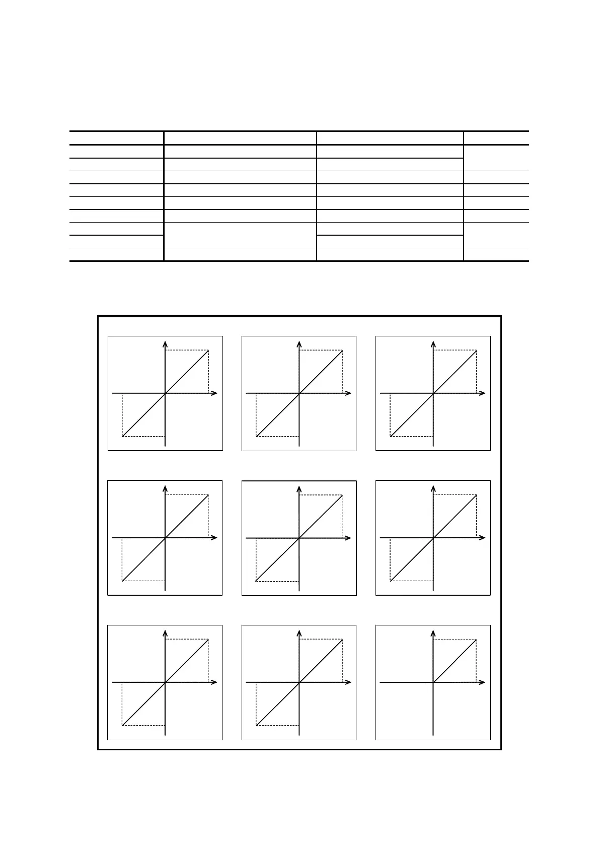
Fig 7-34: Preset analog monitor
Current velocity (MN0•MX0)
+5V
0V
– direction
10 [s
-1
]
+ direction
10 [s
-1
]
øU current
(MN4•MX4)
+5V
Command velocity (MN1•MX1)
+5V
0V
– direction
10 [s
-1
]
+ directio
10 [s
-1
]
Velocity error (MN2•MX2)
+5V
0V
– direction
1.25 [s
-1
]
+ direction
1.25 [s
-1
]
Torque command
(MN3•MX3)
+5V
0V
– direction
100 [%]
+ direction
100 [%]
Transient positon command
(MN5•MX5)
0V
– direction
10 [s
-1
]
+ direction
10 [s
-1
]
+5V
Residual pulses in position error
counter (MN6•MX6)
+5V
0V
– direction
127 [pulse]
+ direction
127 [pulse]
Residual pulse in position error
counter (MN7•MX7)
+5V
0V
– direction
16383 [pulse]
+ direction
16383 [pulse]
Software thermal loading
(MN8•MX8)
+5V
Loading
100 [%]
+2.5V
+2.5V
+2.5V
+2.5V
0V
+2.5V
+2.5V
+2.5V
+2.5V
;+2.5V
100 [%]
100 [%]

 Loading...


