— 2-6 —
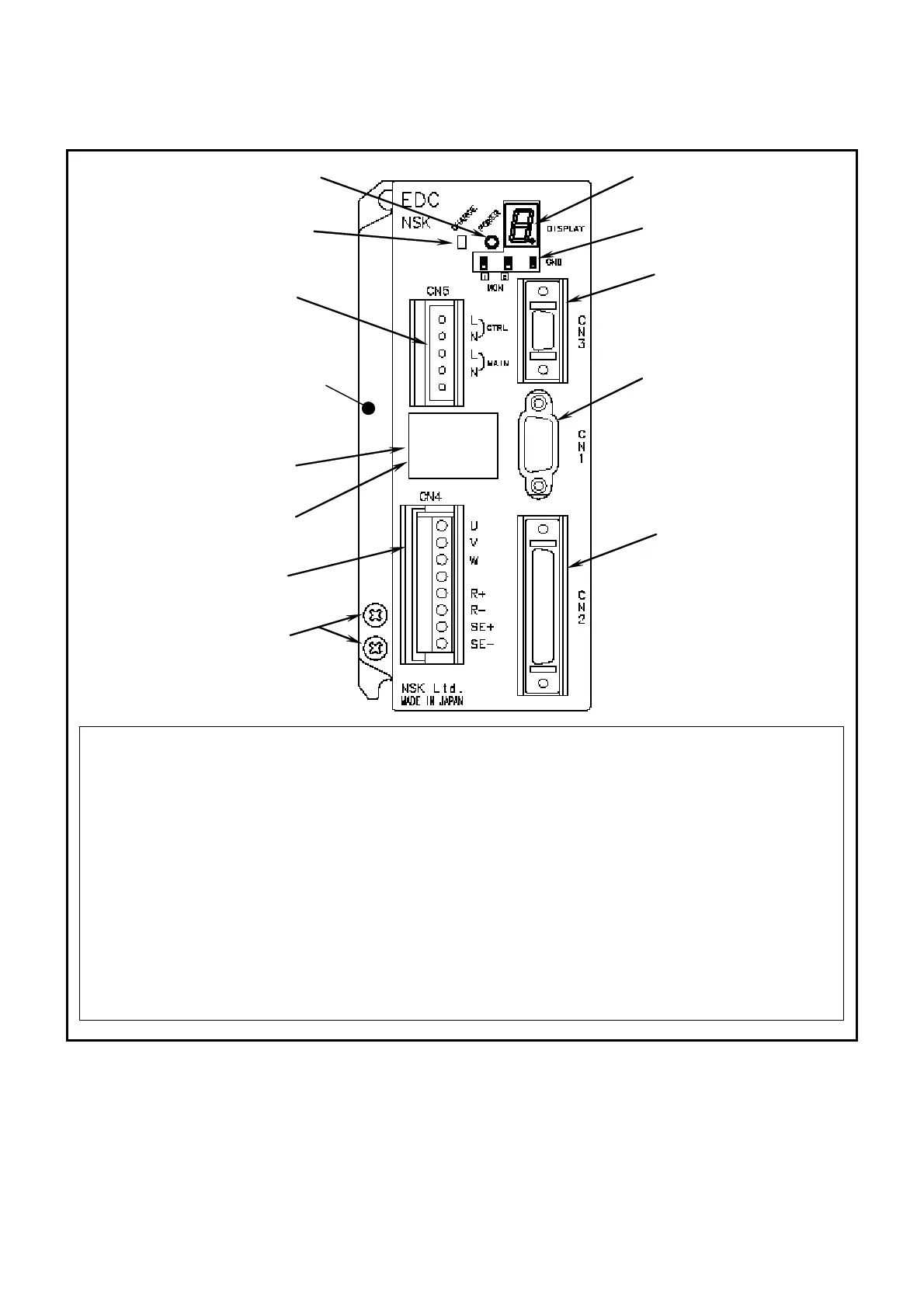
2.3.2. EDC Driver Unit
Fig 2-9: EDC Driver Unit (standard)
(1) Power LED
(2) 7 segments LED
(3) CN1 (9 pins)
RS-232C serial communication cable connector
Connect the optional Handy Terminal FHT21.
(4) CN2 (50 pins)
Motor control Input/Output signal (I/O) connector
(5) CN3 (14 pins)
Resolver cable connector
Connect the exclusive resolver cable.
(6) CN4
Motor cable connector
Connect the exclusive Motor cable.
(7) Ground terminal.
M4 screws
(8) Type
Reference number plate
(9) No.
Serial number plate
(10)Monitor terminal
(11)CN5
Connector for main power
(12)Power amplifier charge indicator
Indicates that the capacitor of the power
amplifier still charges residual voltage.
(2)
Heatsink
1
(3)
(4)
(5)
7
(6)
(8)
9
(10)
(11)
(12)

 Loading...


