— 2-7 —
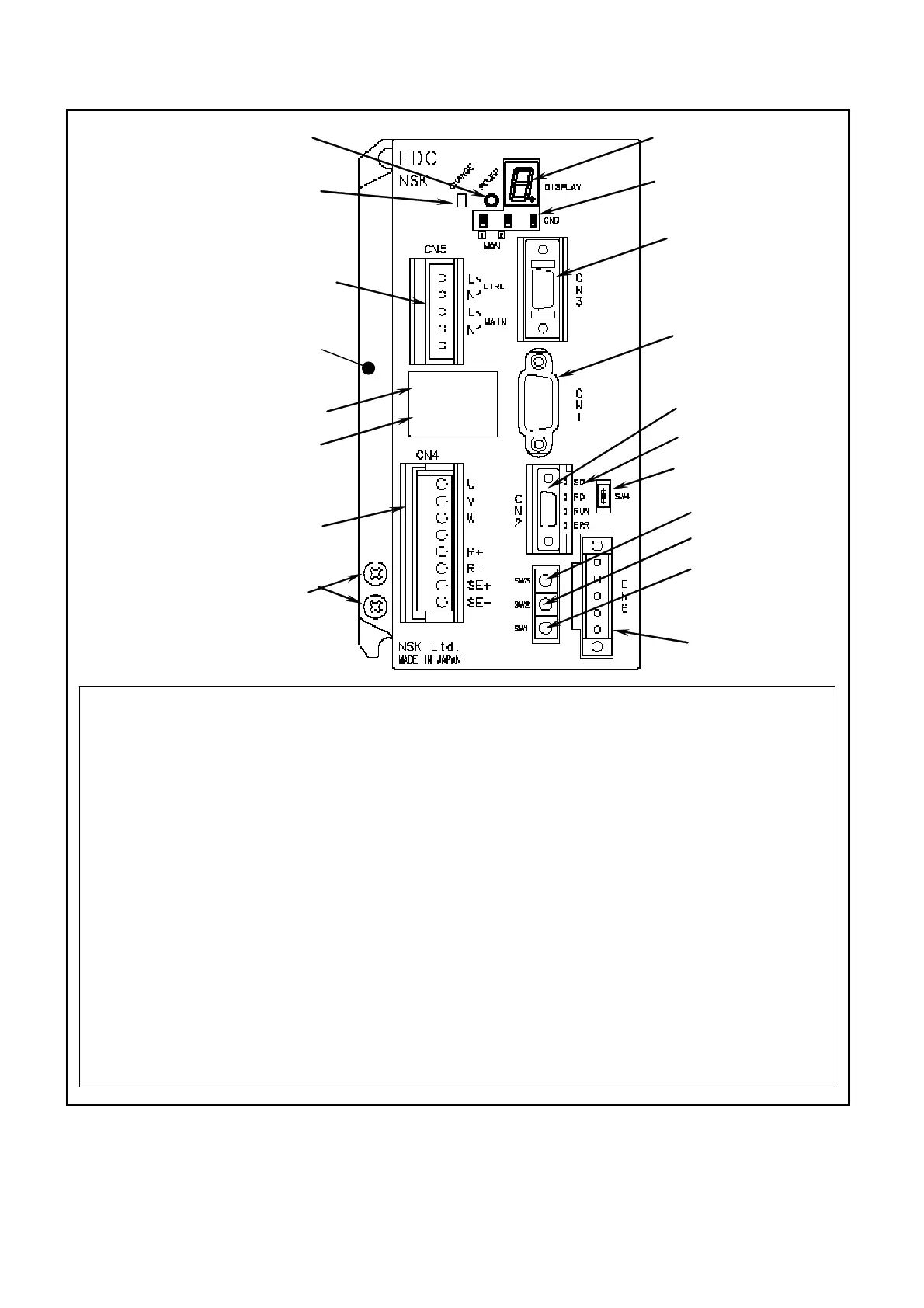
Fig 2-10: EDC Driver Unit compatible with CC-Link
(1)
Main power LED
(2)
7 segments LED
(3)
CN1 (9 pins)
RS-232C serial communication connector
Connect the optional Handy Terminal FHT21.
(3)
CN2 (10 pins)
Motor control Input/Output (I/O) signal connector
(5)
CN3 (14 pins)
Resolver cable connector
Connect the exclusive resolver cable.
(6)
CN4
Motor cable connector
Connect the exclusive Motor cable.
(7)
Ground terminal
M4 screw
(8)
Type
Reference number plate
(9) No.
Serial number plate
(10)Monitor pins
(11)CN5
Main power connector
(12)Power amplifier charge indicator
Indicates that the capacitor of the power
amplifier still charges residual voltage.
(13)CN6
CC-Link connector
(14)SW4
Switch for the terminating resistance
(15)SW1
Station number setting switch (×10)
(16)SW2
Station number setting switch (×1)
(17)SW3
Baud rate setting
(18)Monitor LED
2
Heatsink
3
4
(5)
7
6
8
9
10
(11)
18
17
16
15
14
13
(12)
1

 Loading...


