— 3-7 —
3.3.3. Ground Connection
For grounding the Driver Unit, use braided copper cable or heavy gage cable as possible such as
AWG12 or larger.
The ground terminal is M4 screw. There is a possibility that the thread of a screw is damaged
when the tightening torque of the screw exceeds maximum value 1.2N・m.
!
Caution : Ground the Motor separately when it is isolated from the machine into
which it is installed.
!
Warning : All the ground lines must be connected at one point and the grounding
resistance shall be 100
Ω
or less.
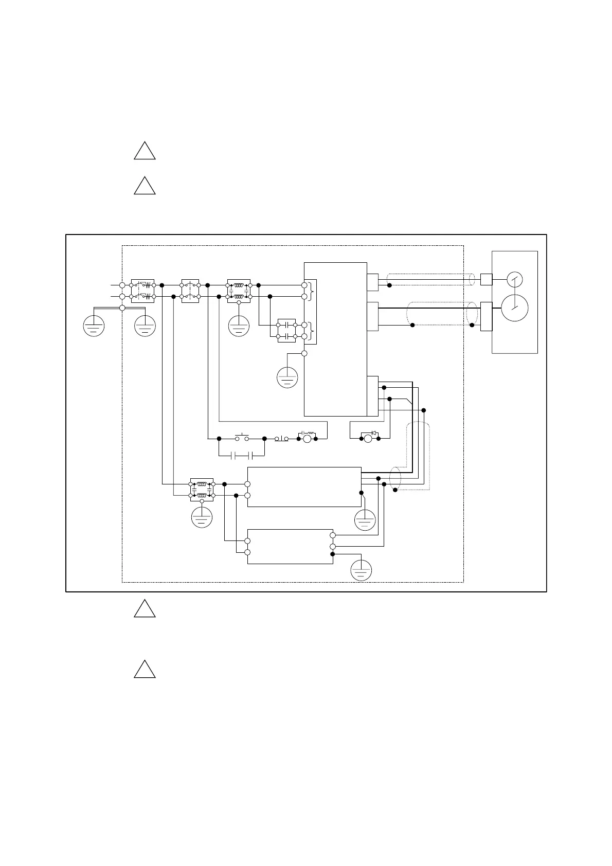
Fig 3-7: Wiring example of power supply
∗1
∗1
∗1:
Connect at one point.
∗1
1
Resolver
Motor
Driver Unit
AC power
Ground earth
Class D
or better
FG
Main power
CN5
Control power
Master controller
• Controller (pulse train output)
• Sequencer
24 VDC
power supply
CN4
CN2
CN3
1
∗1
ELB1
MC1
npu
s
gna
+ 24
DRD
COM
RY1
NF1
+ 24
GND
ELB1: Short circuit breaker
CB1: No fuse breaker
NF1: Noise filter
MC1: Magnetic switch
RY1: Relay
SW1: Main power switch ON
SW2* Main switch OFF
NF
SW1 SW2
MC1
MC1RY1
CB1
!
Caution : We recommend the noise filter below for compliance with the EMC
Directive.
◊ FN2070-10/06 (Schaffner EMC Ltd.) or equivalent.
(Use a breaker compatible with the European Safety Directives.)
!
Caution : Provide a circuit to shut down the main power by the output of an
alarm.
◊ When an alarm occurs, the output DRDY (Driver Unit ready) of the
connector CN2 opens.
The Driver Unit gives the warning P5 (Main AC line low voltage) when the main power is
turned off while the servo is on. [For the main power ON/OFF, refer to “7.1.1. Servo on:
SVON.”]
◊ Input of ACLR (Alarm clear) signal, the command CL (Alarm clear), or turning on the
control power again will clear the alarm.

 Loading...


