— 8-21 —
8.3.3. Travel Limit Output (±): OTXA
Reports that the Motor gets in the area specified by the travel limits.
(For both cases of software and hardware over travel limits.)
Different from the outputs OTPA and OTMA, there is no function to distinguish the direction of
limit switch.
Table 8-21: Signal logic of the output OTXA
Logic Description
Open
Normal
Closed
Limit activated
When the travel limit activates, the following alarms will occur.
Table 8-22: Indicaiton of 7 segments LED at activation of over travel limit
7segmetns LED Command TA (Tell alarm) Description
F2
F2>Software Over Travel
Software over travel
F3
F3>Hardware Over Travel
Hard ware over travel
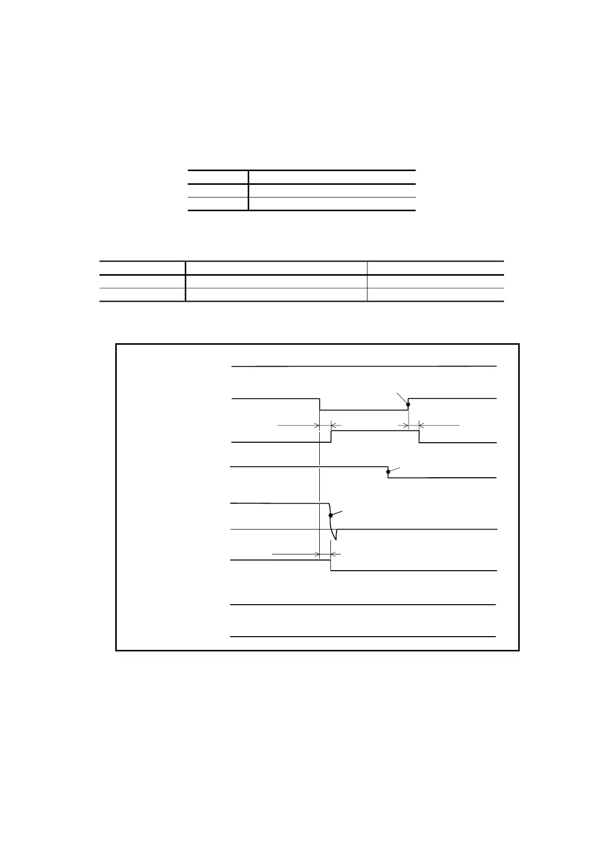
Fig 8-10: Motion timing with the input OTP and the output OTXA (In case of positive logic)
The Motor stops immediately with the Motor
servo on.
Motor motion
closed
open
closed
opem
Ouput DRDY
Input OTP
Outpu SVST
closed
open
closed
open
Output BUSY
closed
open
closed
open
Output IPOS
(FW
> 0: FIN
)
Output OTXA
ON
OFF
Max. 1 ms Max. 1 ms
Max. 1 m
Output IPOS
(FW <
0: CFIN)
(FW
=
0:IPOS
)
Put the Motor in servo-off state by
the input SVON.
Move the Motor out of the area, or turn off the
Motor servo and move the Motor manually
When a travel limit is detected in the middle of operation, the Motor stops before it reaches the
target position. Thus, the output IPOS (In-position) does not close.
When the travel limit is detected while the Motor is stopping, the output IPOS does not change
because the System maintains the position at where the last positioning was completed.
 Loading...


