— 6-33 —
The following describe the procedures of a typical RS-232C communication positioning.
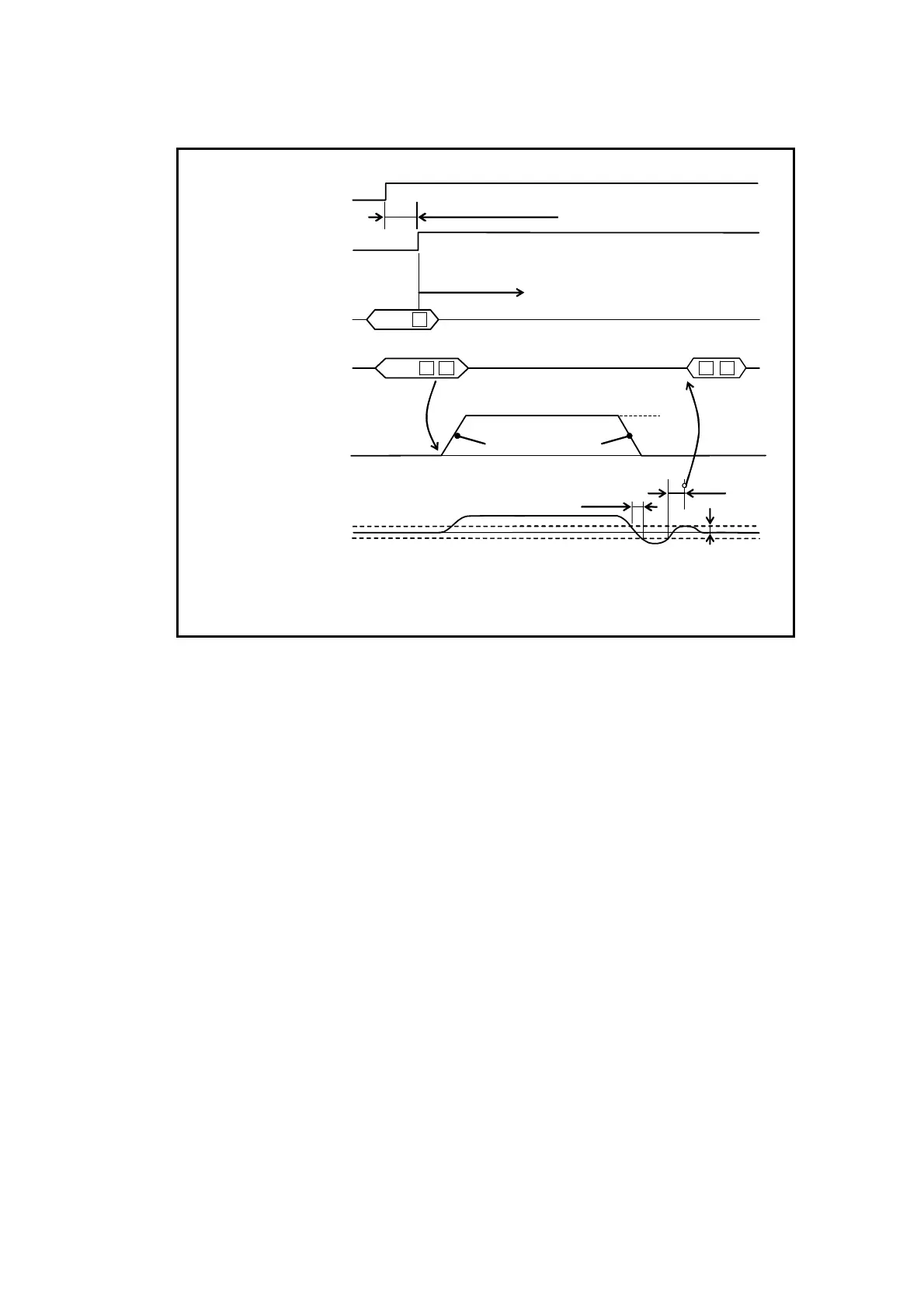
Fig 6-23: Signal timing of an RS-232C communication positioning
Residual pulse in
the position error
counter
IN value
Motor motion
< 100ms
100 ms
Stability timer
Example: IS100 (100ms)
Max. 170 ms (Max. 3.2 s) *1
ON
OFF
closed
open
SVON input
SVST output
RS-232C communication
command
MA
(1)
(2)
(3)
IR100CR
Positioning validated.
*2
RS-232C comunication
acknowledgment
IR100CR LF:
*2
MB
MV
!CR LF:
*2
(4)
*1: It takes 3.2 seconds to activate the Motor servo for the
first time after turning on the main power.
*2: CR: Carriage return code 0D
H
LF : line feed return code 0A
H
1) Activate the input SVON (Servo on) to turn the Motor servo on.
2) When the Motor servo is on, the output SVST (Servo state) closes. This is the state
when the command can be inputted. If you do not check the output SVST, provide
delayed timing after an activation of the input SVON as shown in Figure 6-23.
3) The positioning operation starts right after the input of positioning command.
The positioning is executed following the parameter values of MA (Rotational
acceleration), MB (Rotational deceleration) and MV (Motor velocity).
4) The positioning complete when the position error counter clears the condition set by
the values of parameter IN (In-position) and IS (IN-position stability timer). If the
parameter EC (End code) is set to EC!, completion of positioning is notified by “!”.

 Loading...


