— 8-40 —
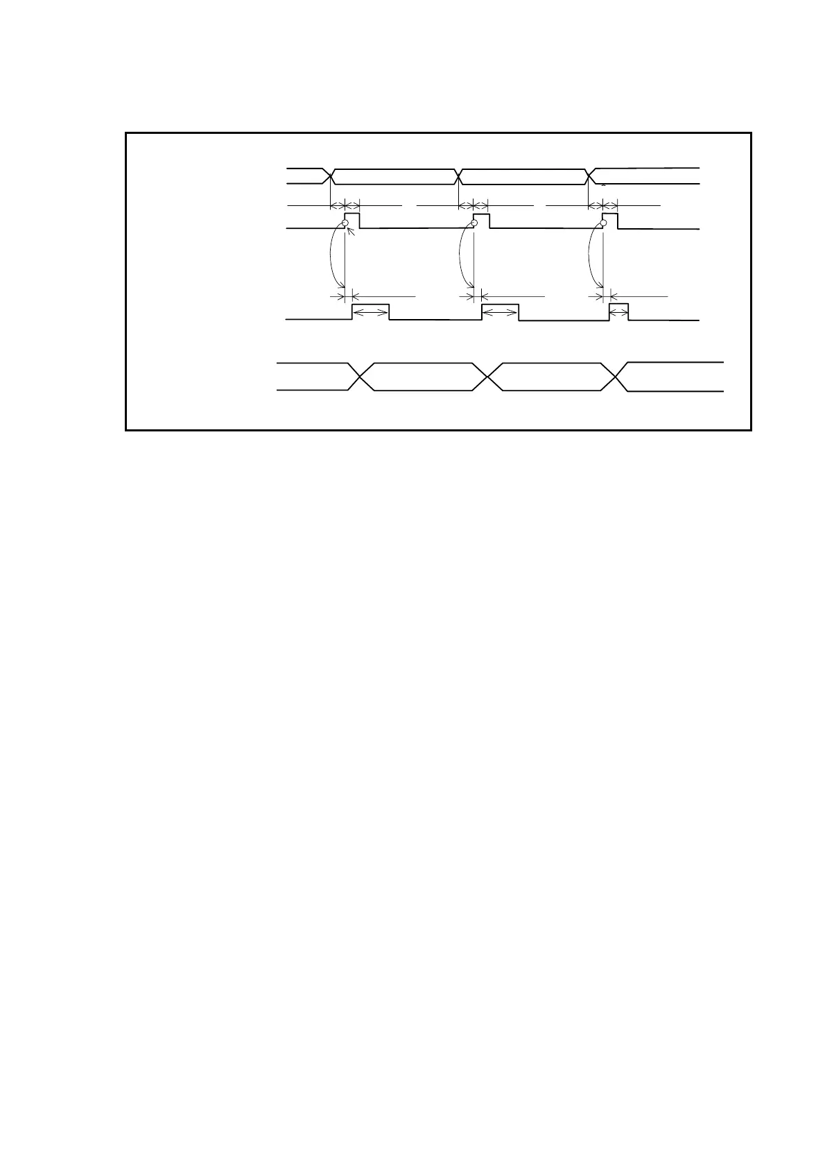
The figure below illustrates signal timing for use of three different gain settings.
Fig 8-21: Signal timing for use of three different gain settings
Selection of channel 0
The rising edge
triggers operation.
Min. 1ms .Min. 1ms
Max. 0.5 ms
Channel selection
(PRG0 to 7inputs)
Inpuf RUN
ON
OFF
closed
open
Output BUSY
Max. 0.5 ms Max. 0.5 ms
O0.12,SG10
100
Channel 0 Channel 1 Channel 2
O0.20,SG14
N100
LO0.05,SG6
IN400
Min. 1ms Min. 1ms Min. 1ms Min. 1ms
Selection of channel 1 Selection of channel
Default Mounted load A Mounted load B Default
1) 2) 3) 4)
Applicable parameter
LO0.05,SG6
IN400
1) Before execution of channel program, the default setting (global parameter) is
effective.
2) When program execution of channel 0 starts, the parameter for the mounted load A
becomes effective.
At this moment, the parameter for the mounted load A remains effective after the
program execution because the parameter PK (Parameter keep) is set to PK1.
3) When program execution of channel 1 starts, the parameter changes to that of the
mounted load B.
4) The parameter RE (Return) is set to the program of channel 2.
Execution of channel 2 program resets to the default parameter cancelling the
parameter for the mounted load B that has been effective.
Approximately 0.1 ms is required for setting one parameter to a program channel.
◊ Chang of parameter setting which entails indirect changes of other parameters, such as
between the parameter SG (servo gain) and parameters PG and VG, require the time
for changing all settings. Thus, it takes approximately 0.3 [ms] for changing the setting
of the parameter SG.

 Loading...


