Conditions to Conform with EC Directives
The wiring example shown below is one of our recommendations for the conformity with the EC Directives.
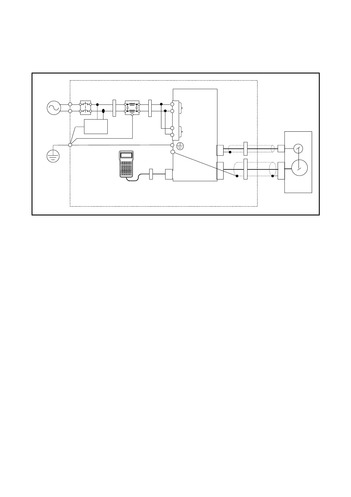
Figure 1: Wiring diagram (Example)
Resolver
EDC Driver Unit
AC power
source
Protective
ground
Main
power
CN5
Control
power
CN4
CN3
Noise
filter
Circuit
breaker
L
N
L
N
Inside of
control
panel
CN1
Handy
Terminal
Ferrite
core 1
3 turns
Ferrite
core 3
(1 turn)
Ferrite core 3
(2 turns)
Ferrite
core 3
(1 turn)
PS Series
Megatorque Motor
Motor
Surge
absorber
Ferrite
core 2
2 turns
Environmental conditions
The Driver Unit must be used in the environmental condition of Pollution Degree1 or 2 as specified
by IEC60664-1. The Driver Unit shall be installed into a control panel with the structure that does not
allow penetration of water, oil or dust (IP54).
Power source
The EDC Driver Unit shall be used in the environmental condition of “Over-voltage category III” as
specified by IEC60664-1.
Circuit breaker
Install a circuit breaker that conforms to IEC standard and UL safety standard between the power
source and the Driver Unit.
Noise filter
Install a noise filter between the power source and the Driver Unit.
Ferrite core
Ferrite cores for signal cable shall be set to the power cable, the Motor cable and the resolver cable.
Protective Grounding
Be sure to ground the protective grounding terminal of the EDC Driver Unit to the protective ground
(PE) of the control panel for a measure against electrical shock.
 Loading...


