ExpressionMR400InstructionsforUseImportantInformation1‐19
Rear Panel Connections
DependingupontheoptionsincludedwithyourMR400ortheusemodel,someconnectionsmay
berequiredaftermovingtheMR400intotheMRmagnetroom.Inaddi tiontotheconnectionfor
ACmainspower,connectionsforthewastegasportandthegatingcableareavailableonthe
rearpanel
oftheMR400.(ForinformationabouttheplacementoftheMR400intheMRmagnet
room,seepage3‐2.)
When making connections to the rear panel of the MR400, ensure that the final installation
complies with IEC 60601-1, clause 16, Medical Electrical (ME) Systems, to assure operator and
patient safety. Always check the summation of leakage currents when the MR400 is connected to
additional external equipment.
Wheretheintegrityoftheexternalprotectiveconductorintheinstallationoritsarrangementis
indoubt,theMR400shallbeoperatedfrombatteries.
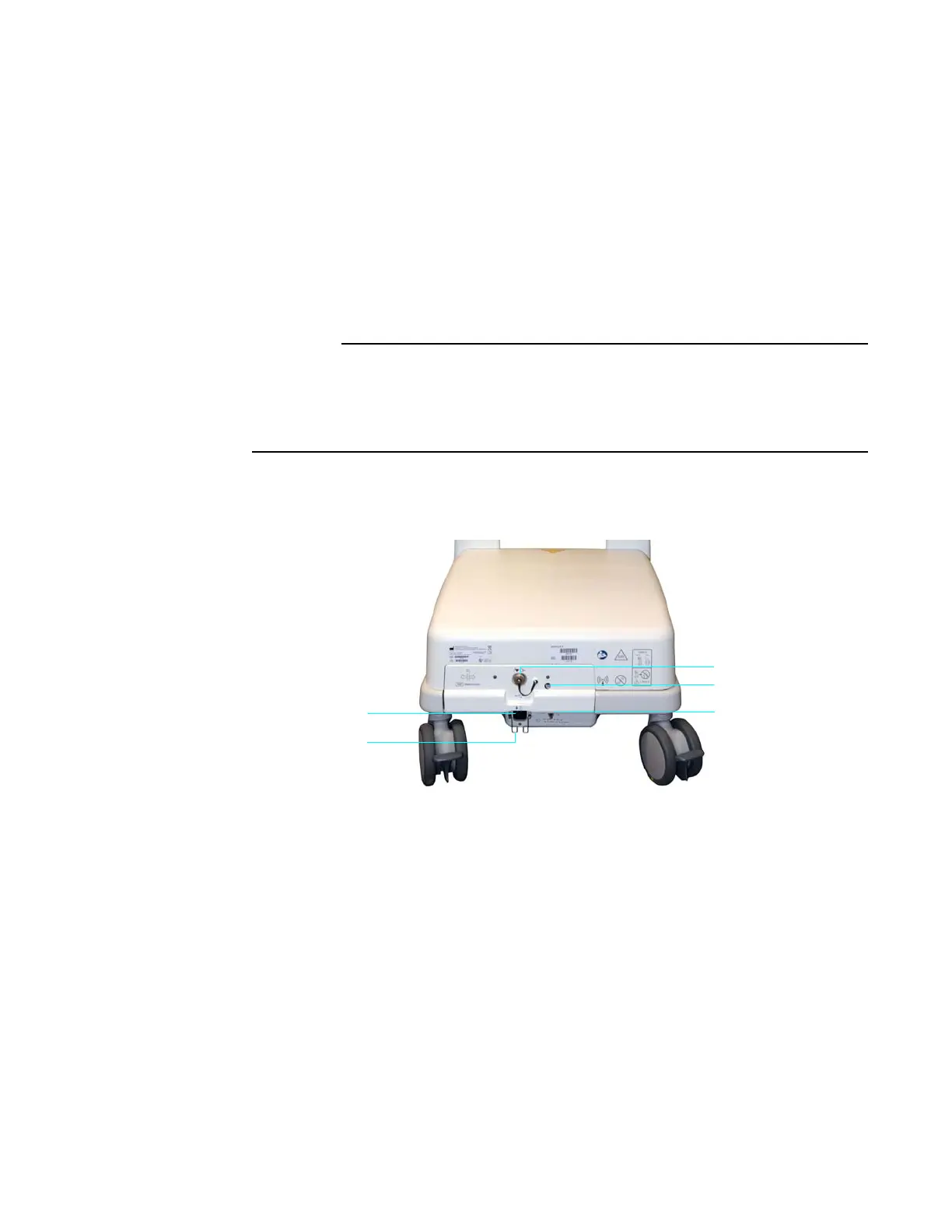
1 Gating connector for gating control connections to the MR
system. (Gating cables are type-dependent; see page 1-35.)
2Waste gas port (if equipped) for connection of exhausted sam-
pled respiratory gases from the MR400 to your facility’s gas scaveng-
ing system; suggested tubing requirement: 3.175 mm (0.125 inch)
outer diameter, 1.6 mm (0.063 inch) inner diameter.
3 Ground lug (equipotential ground [earth] connection point)
• allows for electrical safety testing; and,
• allows authorized service personnel to connect a ground
strap for prevention of ESD during servicing.