ExpressionMR400Instructionsfor UseSystemOverview2‐7
Patient Connection Panel
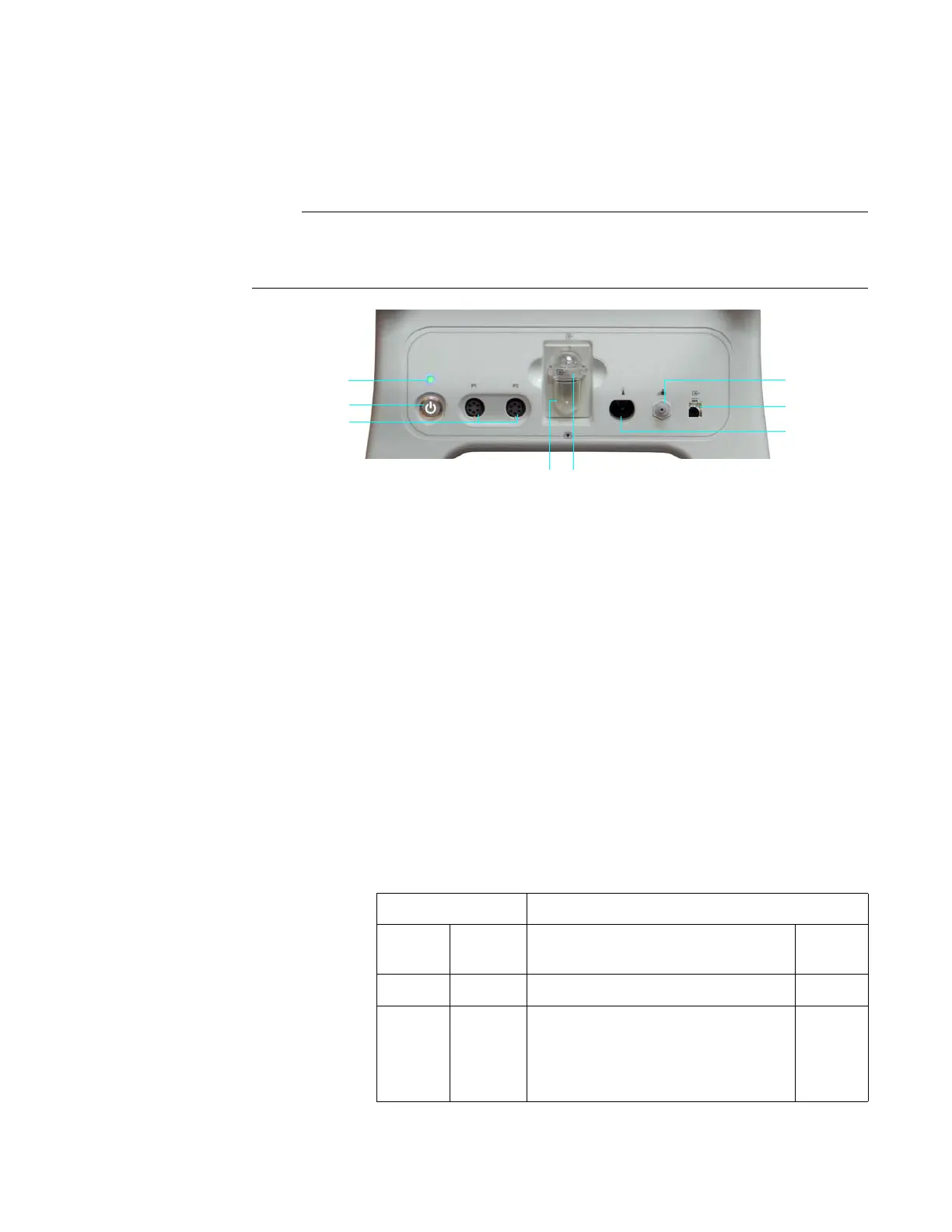
ThepatientconnectionpanelcontainsthepowerswitchandLED,andinputconnectionsfor
variouspatientaccessories.
The illustration shown below features a composite of all available options. Your MR400 will not
have all of these options.
1 NIBP interconnect hose port
2 (Optional) Loflo CO2 sampling line port
3 (Optional) Temperature port
4 (Optional) AGENT sample port
5 (Optional) AGENT water trap
6 (Optional) Invasive blood pressure ports (P1 and P2)
7 Power switch (standby switch) is a push-type latching switch that
controls power (AC mains or batteries) to the MR400
8 Power LED indicates the power source and power status of the
MR400, as detailed in the table below
Power LED Condition / Meaning
Color State Power Source
Power
Switch
None Off None (batteries may be installed) Off
Green Steady Depending upon power source:
• If AC is present, then AC mains
• If AC is not present, then
batteries
On