RL78/G10 CHAPTER 6 TIMER ARRAY UNIT
R01UH0384EJ0311 Rev. 3.11 165
Dec 22, 2016
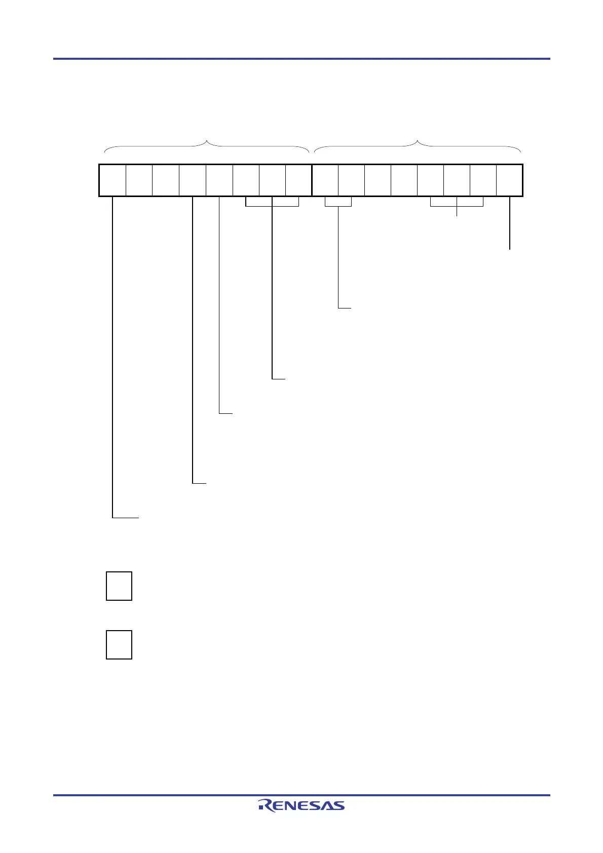
Figure 6-46. Example of Set Contents of Registers in External Event Counter Mode (1/2)
(a) Timer mode register 0n (TMR0nH, TMR0nL)
TMR0nH TMR0nL
7 6 5 4 3 2 1 0 7 6 5 4 3 2 1 0
TMR0n
CKS0n1
1/0
0
0
CCS0n
1
M/S
Note
0/1
STS0n2
0
STS0n1
0
STS0n0
0
CIS0n1
1/0
CIS0n0
1/0
0
0
MD0n3
0
MD0n2
1
MD0n1
1
MD0n0
0
Operation mode of channel n
011B: Event count mode
Setting of operation when counting is started
0: Neither generates INTTM0n nor inverts
timer output when counting is started.
Selection of TI0n pin input edge
00B: Detects falling edge.
01B: Detects rising edge.
10B: Detects both edges.
11B: Setting prohibited
Start trigger selection
000B: Selects only software start.
Setting of MASTER0n bit (Channel 2)
0: Independent channel operation
Setting of SPLIT0n bit (Channel 1, 3)
0: 16-bit timer
1: 8-bit timer
Count clock selection
1: Selects the TI0n pin input valid edge.
Operation clock (fMCK) selection
0: Selects CK00 as operation clock of channel n.
1: Selects CK01 as operation clock of channel n.
(b) Timer output register 0 (TO0)
Bit n
TO0
TO0n
0
0: Outputs 0 from TO0n.
(c) Timer output enable register 0 (TOE0)
Bit n
TOE0
TOE0n
0
0: Stops the TO0n output operation by counting operation.
Note TMR02: MASTER0n bit
TMR01, TMR03: SPLIT0n bit
TMR00: 0 fixed
Remark n: Channel number
n = 0, 1 (for 10-pin products); n = 0 to 3 (for 16-pin products)

 Loading...


