RL78/G15 CHAPTER 4 PORT FUNCTIONS
R01UH0959EJ0110 Rev.1.10 Page 110 of 765
Mar 7, 2023
4.3.5 Port mode control registers 0, 2 (PMC0, PMC2)
These registers set the digital I/O/analog input in 1-bit units.
These registers can be set by a 1-bit or 8-bit memory manipulation instruction.
Reset signal generation clears these registers to FFH.
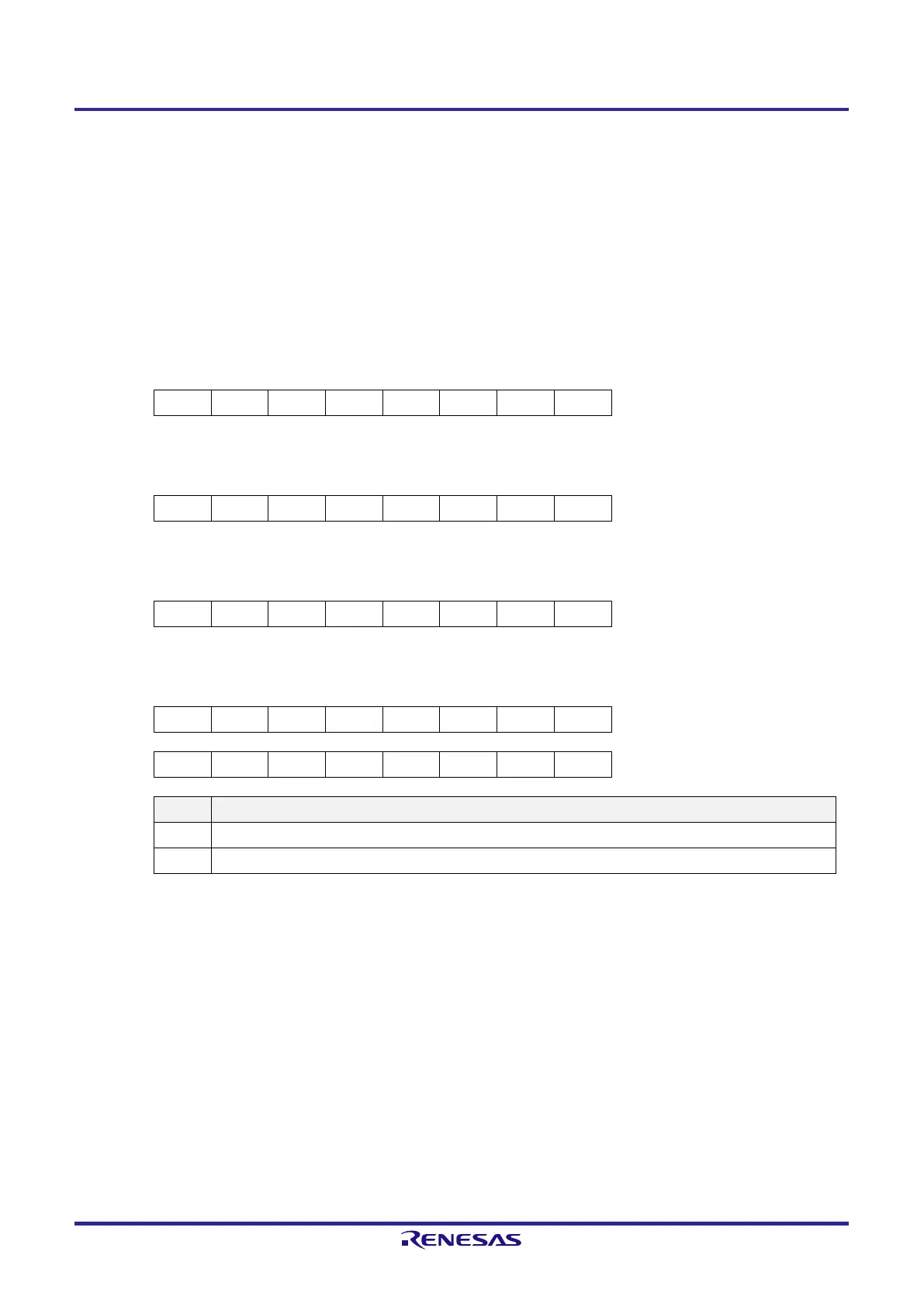
Figure 4-5. Format of Port Mode Control Registers 0, 2 (PMC0, PMC2)
8-pin products
Symbol 7 6 5 4 3 2 1 0 Address After reset R/W
PMC0 1 1 1 PMC04 PMC03 1 PMC01 1 F0060H FFH R/W
10-pin products
Symbol 7 6 5 4 3 2 1 0 Address After reset R/W
PMC0 1 1 1 PMC04 PMC03 PMC02 PMC01 1 F0060H FFH R/W
16-pin products
Symbol 7 6 5 4 3 2 1 0 Address After reset R/W
PMC0 PMC07 PMC06 PMC05 PMC04 PMC03 PMC02 PMC01 1 F0060H FFH R/W
20-pin products
Symbol 7 6 5 4 3 2 1 0 Address After reset R/W
PMC0 PMC07 PMC06 PMC05 PMC04 PMC03 PMC02 PMC01 1 F0060H FFH R/W
PMC2 1 1 1 1 PMC23 PMC22 PMC21 PMC20 F0062H FFH R/W
PMCmn P0n pin digital I/O/analog input selection
0 Digital I/O (alternate function other than analog input)
1 Analog input
Remark m = 0, 2
n = 1 to 7
Caution 1. Select input mode by using port mode registers 0, 2 (PM0, PM2) for the ports which are set by the
PMC0, PMC2 registers as analog input.
Caution 2. Be sure to set bits that are not mounted to their initial values.
 Loading...


