RL78/G15 CHAPTER 19 FLASH MEMORY
R01UH0959EJ0110 Rev.1.10 Page 658 of 765
Mar 7, 2023
19.1.1 Programming environment
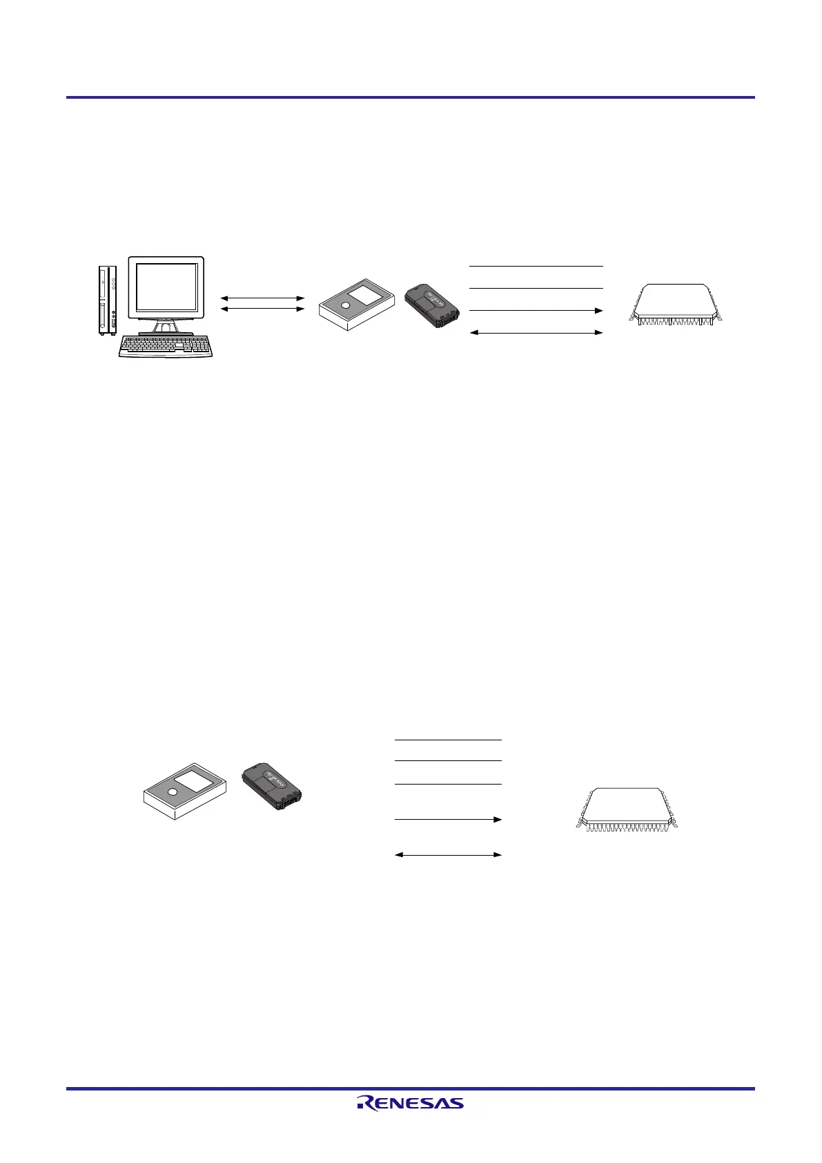
The environment required for writing a program to the flash memory of the RL78 microcontroller is illustrated below.
Figure 19-1. Environment for Writing Program to Flash Memory
TOOL0 (dedicated single-line UART)
Dedicated flash
memory programmer
RL78 microcontroller
PG-FP6
RS
-232
C
Host machine
USB
V
DD
V
SS
E
2, E2 Lite
______
RESET
A host machine that controls the dedicated flash memory programmer is necessary.
To interface between the dedicated flash memory programmer and the RL78 microcontroller, the TOOL0 pin is used for
manipulation such as writing and erasing via a dedicated single-line UART.
19.1.2 Communication mode
Communication between the dedicated flash memory programmer and the RL78 microcontroller is established by serial
communication using the TOOL0 pin via a dedicated single-line UART of the RL78 microcontroller.
Transfer rate: Fixed to 115200 bps
Figure 19-2. Communication with Dedicated Flash Memory Programmer
V
DD
______
RESET
TOOL0
GND
Dedicated flash
memory programmer
PG-
FP6
E2,
E2 Lite
V
SS
V
DD
EMV
DD
Note 1
FLMD1
Note 2
V
DD
Note 3
TOOL0
Note 1
SI/RxD
Note 2
RL78 microcontroller
RESET_OUT
Note
1
______
RESET
Note
2
Note 1. When using E2 or E2 Lite on-chip debugging emulator.
Note 2. When using PG-FP6.
Note 3. The signal name for the PG-FP6 is V
CC
.
 Loading...


