RL78/G15 CHAPTER 10 A/D CONVERTER
R01UH0959EJ0110 Rev.1.10 Page 329 of 765
Mar 7, 2023
10.3.6 Analog input channel specification register (ADS)
This register specifies the input channel of the analog voltage to be A/D converted.
The ADS register can be set by a 1-bit or 8-bit memory manipulation instruction.
Reset signal generation clears this register to 00H.
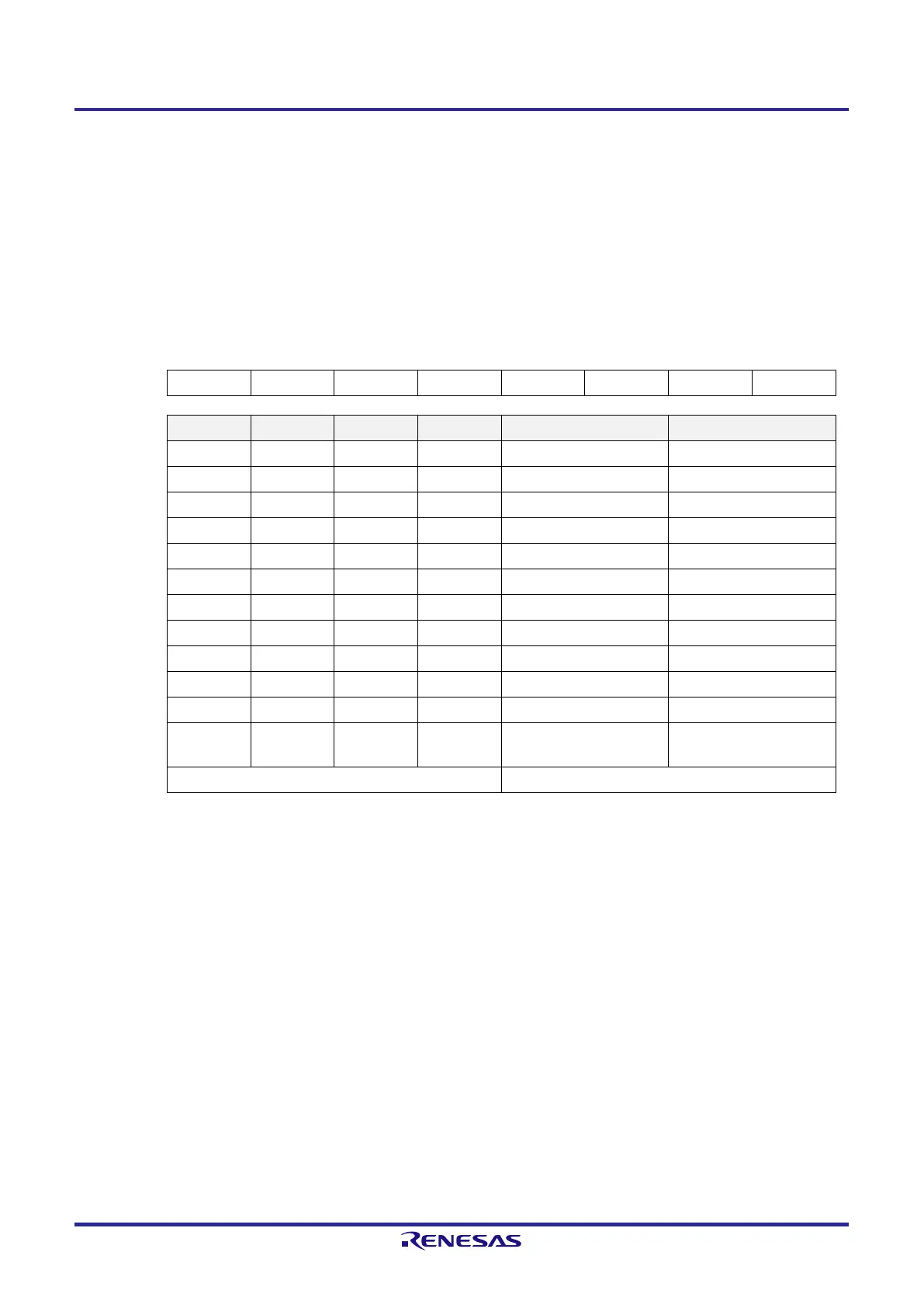
Figure 10-9. Format of Analog Input Channel Specification Register (ADS)
Address: FFF31H After reset: 00H R/W
Symbol 7 6 5 4 3 2 1 0
ADS 0 0 0 0 ADS3 ADS2 ADS1 ADS0
ADS3 ADS2 ADS1 ADS0 Target of A/D conversion Analog input pin
0 0 0 0 ANI0 P01/ANI0 pin
0 0 0 1 ANI1 P02/ANI1 pin
0 0 1 0 ANI2 P03/ANI2 pin
0 0 1 1 ANI3 P04/ANI3 pin
0 1 0 0 ANI4 P05/ANI4 pin
0 1 0 1 ANI5 P06/ANI5 pin
0 1 1 0 ANI6 P07/ANI6 pin
0 1 1 1 ANI7 P23/ANI7 pin
1 0 0 0 ANI8 P22/ANI8 pin
1 0 0 1 ANI9 P21/ANI9 pin
1 0 1 0 ANI10 P20/ANI10 pin
1 1 0 1
Internal reference voltage
(0.815 V (typ.))
Note 1
—
Other than the above Setting prohibited
Note 1. When the internal reference voltage is selected as the target of conversion by the A/D converter, be sure to
clear the LV0 bit in A/D converter mode register 0 (ADM0) to 0.
Caution 1. Only rewrite the ADS register while in the conversion standby state (ADCS = 0, ADCE = 1) or
conversion is stopped (ADCS = 0, ADCE = 0).
Caution 2. For the ports which are used as analog input ports, select input mode with port mode registers 0
and 2 (PM0, PM2) and analog input with port mode control registers 0 and 2 (PMC0, PMC2). Do not
use the ADS register to set the pins which are set as digital I/O with port mode control registers
(PMC0, PMC2).
Caution 3. The internal reference voltage cannot be used for the A/D converter and the comparator
simultaneously. When the internal reference voltage is selected as the target of conversion by the
A/D converter (ADS3 to ADS0 = 1101B), it cannot be set as the reference voltage of the comparator.
Caution 4. Be sure to clear bits 4 to 7 to 0.
 Loading...


