RL78/G15 CHAPTER 13 SERIAL INTERFACE IICA
R01UH0959EJ0110 Rev.1.10 Page 518 of 765
Mar 7, 2023
13.3.3 IICA status register 0 (IICS0)
This register indicates the state of the I
2
C.
The IICS0 register can only be read by a 1-bit or 8-bit memory manipulation instruction while the setting of STT0 is 1 or
during the clock stretch period.
Reset signal generation clears this register to 00H.
Caution Reading the IICS0 register while the address match wakeup function is enabled (WUP0 = 1) in STOP
mode is prohibited. When the WUP0 bit is changed from 1 to 0 (wakeup operation is stopped),
regardless of the INTIICA0 interrupt request signal, the change in the state is not reflected until the
next start condition or stop condition is detected. To use the wakeup function, therefore, enable the
generation of an interrupt on detection of a stop condition (SPIE0 = 1) and read the IICS0 register after
the interrupt has been detected.
Remark STT0: Bit 1 of IICA control register 00 (IICCTL00)
WUP0: Bit 7 of IICA control register 01 (IICCTL01)
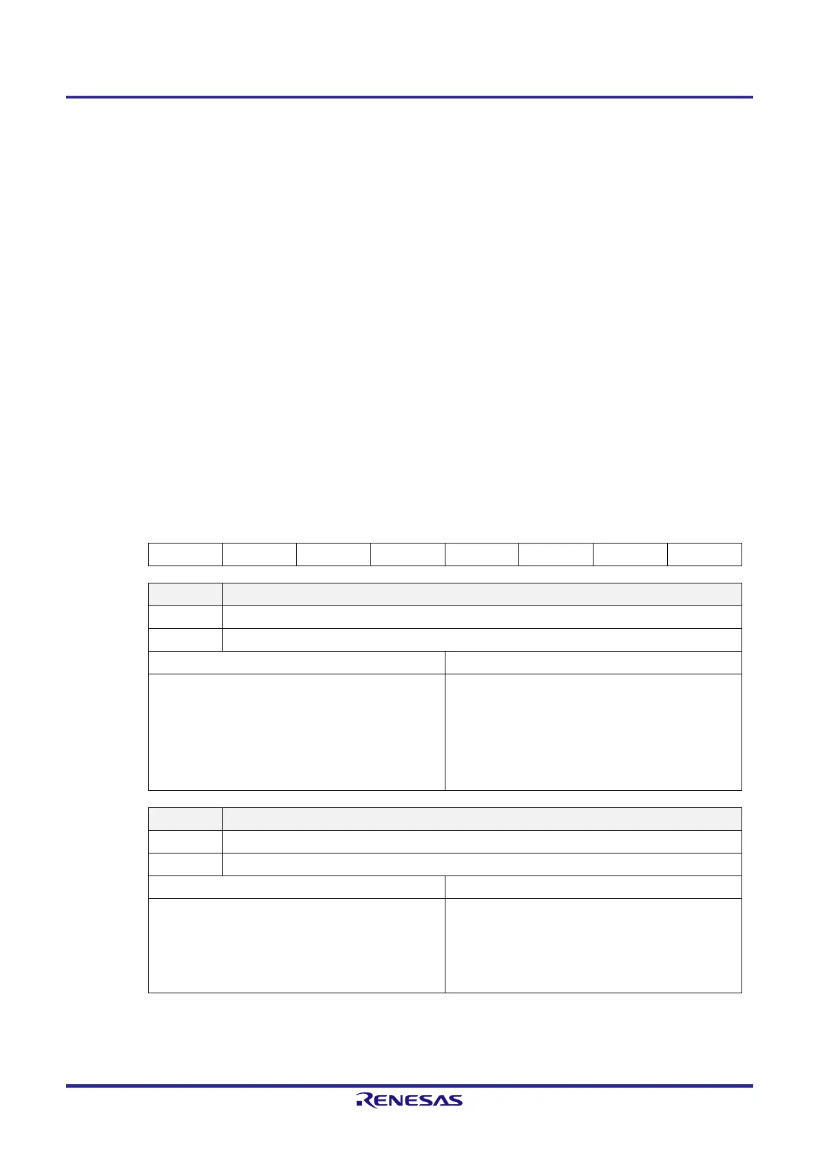
Figure 13-7. Format of IICA Status Register 0 (IICS0) (1/3)
Address: FFF51H After reset: 00H R
Symbol
□
7
□
6
□
5
□
4
□
3
□
2
□
1
□
0
IICS0 MSTS0 ALD0 EXC0 COI0 TRC0 ACKD0 STD0 SPD0
MSTS0 Master state check flag
0 Slave state or communication standby state
1 Master communication state
Condition for clearing (MSTS0 = 0) Condition for setting (MSTS0 = 1)
●
When a stop condition is detected
●
When ALD0 = 1 (arbitration loss)
●
Cleared by LREL0 = 1 (exit from communications)
●
When the IICE0 bit changes from 1 to 0 (operation
stop)
●
Reset
●
When a start condition is generated
ALD0 Detection of arbitration loss
0 Indicates that no arbitration has occurred or a win in arbitration.
1 Indicates a loss in arbitration. The MSTS0 bit is cleared.
Condition for clearing (ALD0 = 0) Condition for setting (ALD0 = 1)
●
Automatically cleared after the IICS0 register has been
read
Note 1
●
When the IICE0 bit changes from 1 to 0 (operation
stop)
●
Reset
●
A loss in arbitration
 Loading...


