RL78/G15 CHAPTER 4 PORT FUNCTIONS
R01UH0959EJ0110 Rev.1.10 Page 118 of 765
Mar 7, 2023
(5) PCLBUZ0 = 0 (setting when clock/buzzer output is not used)
When the clock/buzzer output is not used, set the PCLOE0 bit in clock output select register 0 (CKS0) to 0 (output
disabled). This is the same setting as the initial state.
4.5.3 Register setting examples for used port and alternate functions
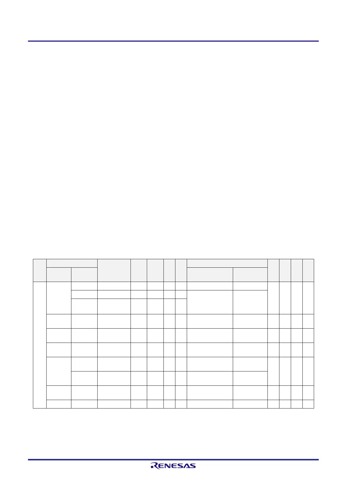
Register setting examples for used port and alternate functions are shown in Table 4-7. The registers used to control
the port functions should be set as shown in Table 4-7. See the following remark for legends used in Table 4-7.
Remark —: Not supported
×: don’t care
PIORr: Peripheral I/O redirection register r (r = 0 to 3)
POMp: Port output mode register p (p = 0, 2, 4)
PMCq: Port mode control register q (q = 0, 2)
PMn: Port mode register n (n = 0, 2, 4, 12)
Pm: Port output latch (m = 0, 2, 4, 12, 13)
Functions in parentheses can be assigned via settings in the peripheral I/O redirection register 0 to 3 (PIOR0
to PIOR3).
Table 4-7. Setting Examples of Registers and Output Latches When Using Pin Function (1/10)
Pin
Name
Used Function PIORr POMp PMCq PMn Pm Alternate Function Output 20-
pin
16-
pin
10-
pin
8-
pin
Function
Name
I/O SAU Output Function Other than SAU
P00 P00 Input — × — 1 × × × —
Output — 0 — 0 0/1 TxD0/SO00 = 1
(SCK01/SCL01) = 1
Note 1
(SCLA0) = 0
Note 1
N-ch open
drain output
— 1 — 0 0/1
SO00 Output PIOR11 = 0
Note 1
PIOR10 = 0
Note 1
0 — 0 1 (SCK01/SCL01) = 1
Note 1
(SCLA0) = 0
Note 1
—
TxD0 Output PIOR11 = 0
Note 1
PIOR10 = 0
Note 1
0/1 — 0 1 (SCK01/SCL01) = 1
Note 1
(SCLA0) = 0
Note 1
—
INTP6 Input PIOR27 = 0
Note 2
PIOR26 = 0
Note 1
× — 1 × × × —
(SCK01) Input PIOR13 = 0
Note 2
PIOR12 = 1
Note 1
× — 1 × × × — —
Output PIOR13 = 0
Note 2
PIOR12 = 1
Note 1
0 — 0 1 TxD0/SO00 = 1 (SCLA0) = 0
(SCL01) Output PIOR13 = 0
Note 2
PIOR12 = 1
Note 1
0 — 0 1 TxD0/SO00 = 1 (SCLA0) = 0 — —
(SCLA0) I/O PIOR14 = 1 1 — 0 0 × × — —
 Loading...


