RL78/G15 CHAPTER 8 CLOCK OUTPUT/BUZZER OUTPUT CONTROLLER
R01UH0959EJ0110 Rev.1.10 Page 310 of 765
Mar 7, 2023
8.4 Operations of Clock Output/Buzzer Output Controller
One pin can be used to output a clock or buzzer sound.
The PCLBUZ0 pin outputs a clock/buzzer selected by clock output select register 0 (CKS0).
8.4.1 Operation as output pin
The PCLBUZ0 pin is output as the following procedure.
1. Set the corresponding bits in the port mode register (PM0/PM4), port register (P0/P4), and port mode control
register 0 (PMC0) for the port pin on which the PCLBUZ0 function is multiplexed to 0.
2. Select the output frequency with bits 0 to 2 (CCS00 to CCS02) of the clock output select register (CKS0) for the
PCLBUZ0 pin (output is disabled).
3. Set bit 7 (PCLOE0) of the CKS0 register to 1 to enable clock/buzzer output.
Remark The controller used for clock output starts or stops clock output one clock after enabling or disabling of clock
output (by the PCLOE bit) is switched. At this time, pulses with a narrow width are not output.
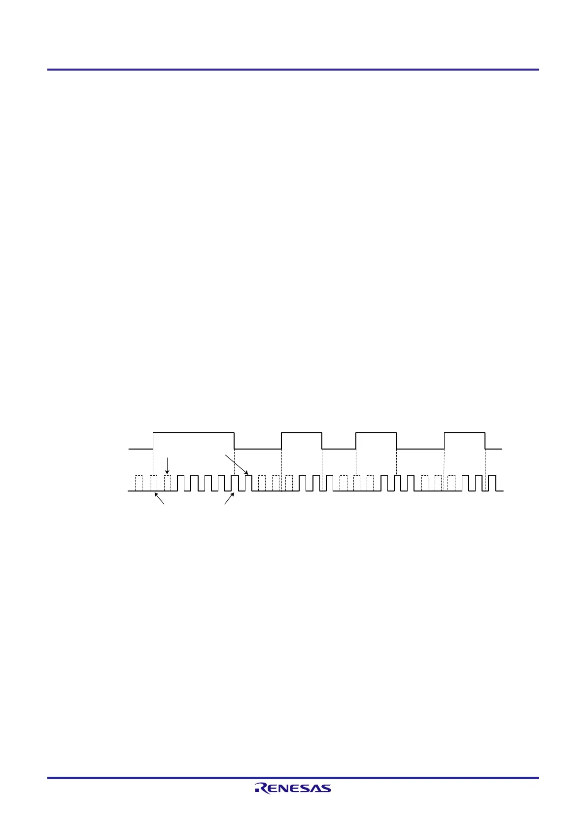
Figure 8-3 shows enabling or stopping of output by the PCLOE0 bit and the timing of clock output.
Figure 8-3. Timing of Clock Output from PCLBUZ0 Pin
PCLOE0
Clock output
Narrow pulses are
not output
1 clock elapsed
Remark If STOP mode is entered within 1.5 clock cycles of the PCLBUZ0 pin output clock after disabling the
PCLBUZ0 pin output (PCLOE0 = 0), the width of the PCLBUZ0 pin output pulse becomes shorter. In
such cases, only execute the STOP instruction after at least 1.5 clock cycles of the PCLBUZ0 pin
output clock have elapsed following disabling of the PCLBUZ0 pin output.
 Loading...


