RL78/G15 CHAPTER 13 SERIAL INTERFACE IICA
R01UH0959EJ0110 Rev.1.10 Page 542 of 765
Mar 7, 2023
13.5.11 Extension code
(1) When the higher 4 bits of the receive address are either “0000” or “1111”, the extension code reception flag
(EXC0) is set to 1 for extension code reception and an interrupt request (INTIICA0) is generated at the falling edge
of the 8th clock.
The local address stored in slave address register 0 (SVA0) is not affected.
(2) If 11110xx0 is transferred from the master in 10-bit address transfer while the SVA0 register is set to 11110xx0,
the settings are as follows. Note that an interrupt request (INTIICA0) occurs at the falling edge of the 8th clock.
●
Higher four bits of data match: EXC0 = 1
●
Seven bits of data match: COI0 = 1
Remark EXC0: Bit 5 of IICA status register 0 (IICS0)
COI0: Bit 4 of IICA status register 0 (IICS0)
(3) Since the processing after the interrupt request occurs differs according to the data that follows the extension
code, such processing is performed by software.
If the extension code is received in slave operation, the slave is participating in communications even with an
address mismatch.
For example, after the extension code is received, if you do not wish to operate the target device as a slave, set bit
6 (LREL0) of IICA control register 00 (IICCTL00) to 1 to set the standby mode for the next communication
operation.
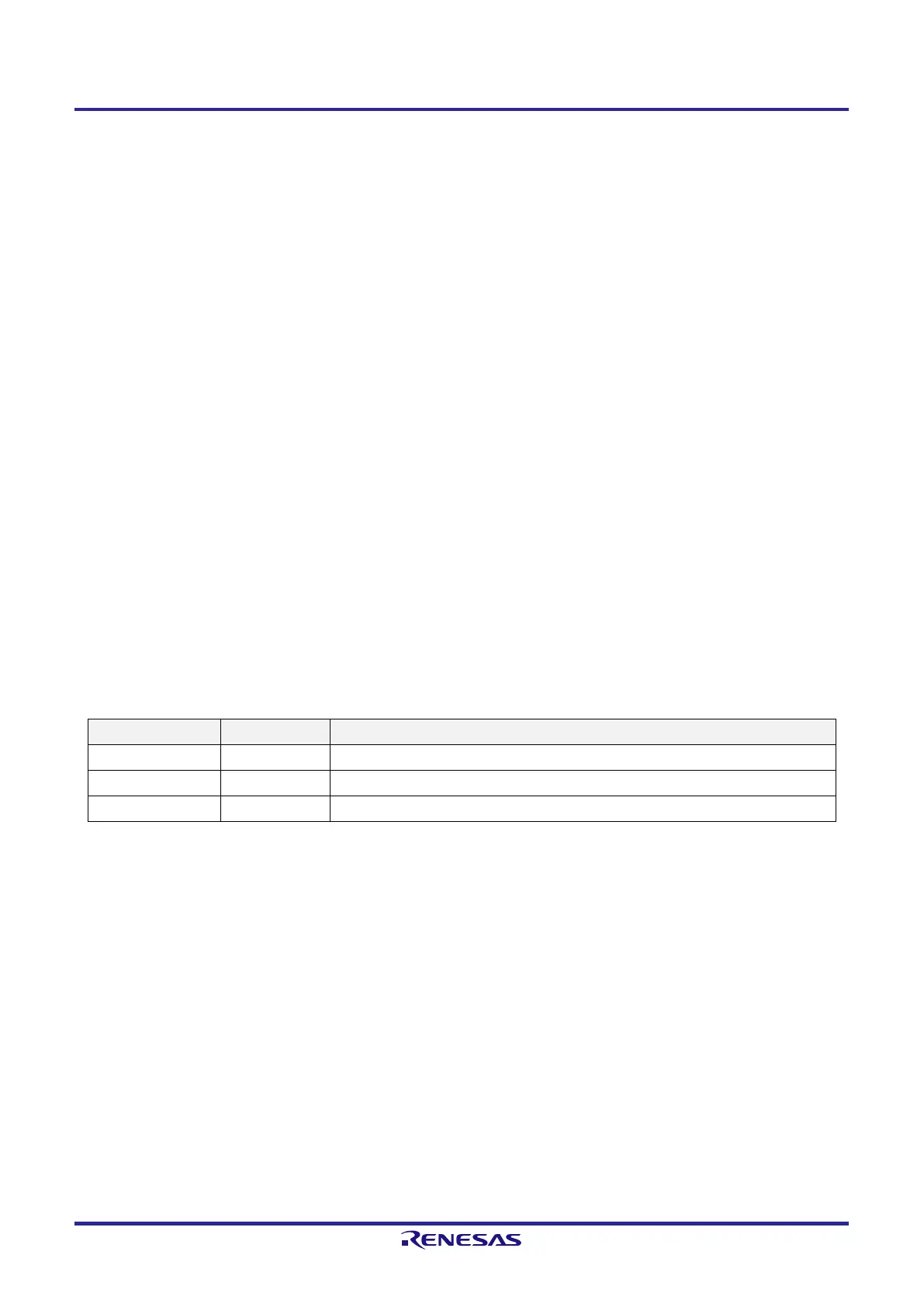
Table 13-3. Bit Definitions of Major Extension Codes
Slave Address R/W Bit Description
0000_000 0 General call address
1111_0xx 0 10-bit slave address specification (for address authentication)
1111_0xx 1 10-bit slave address specification (when read command is issued after address match)
Remark See the I
2
C bus specifications issued by NXP Semiconductors for details of extension codes other than those
described above.
 Loading...


