RL78/G15 CHAPTER 6 TIMER ARRAY UNIT
R01UH0959EJ0110 Rev.1.10 Page 189 of 765
Mar 7, 2023
6.3.4 Timer status register mn (TSRmn)
The TSRmn register indicates the overflow status of the counter of channel n.
The TSRmn register is valid only in the capture mode (MDmn3 to MDmn1 = 010B) and capture & one-count mode
(MDmn3 to MDmn1 = 110B). See Table 6-5 for the operation of the OVF bit in each operation mode and set/clear
conditions.
The TSRmn register can be read by a 16-bit memory manipulation instruction.
The lower 8 bits of the TSRmn register can be read with an 8-bit memory manipulation instruction with TSRmnL.
Reset signal generation clears this register to 0000H.
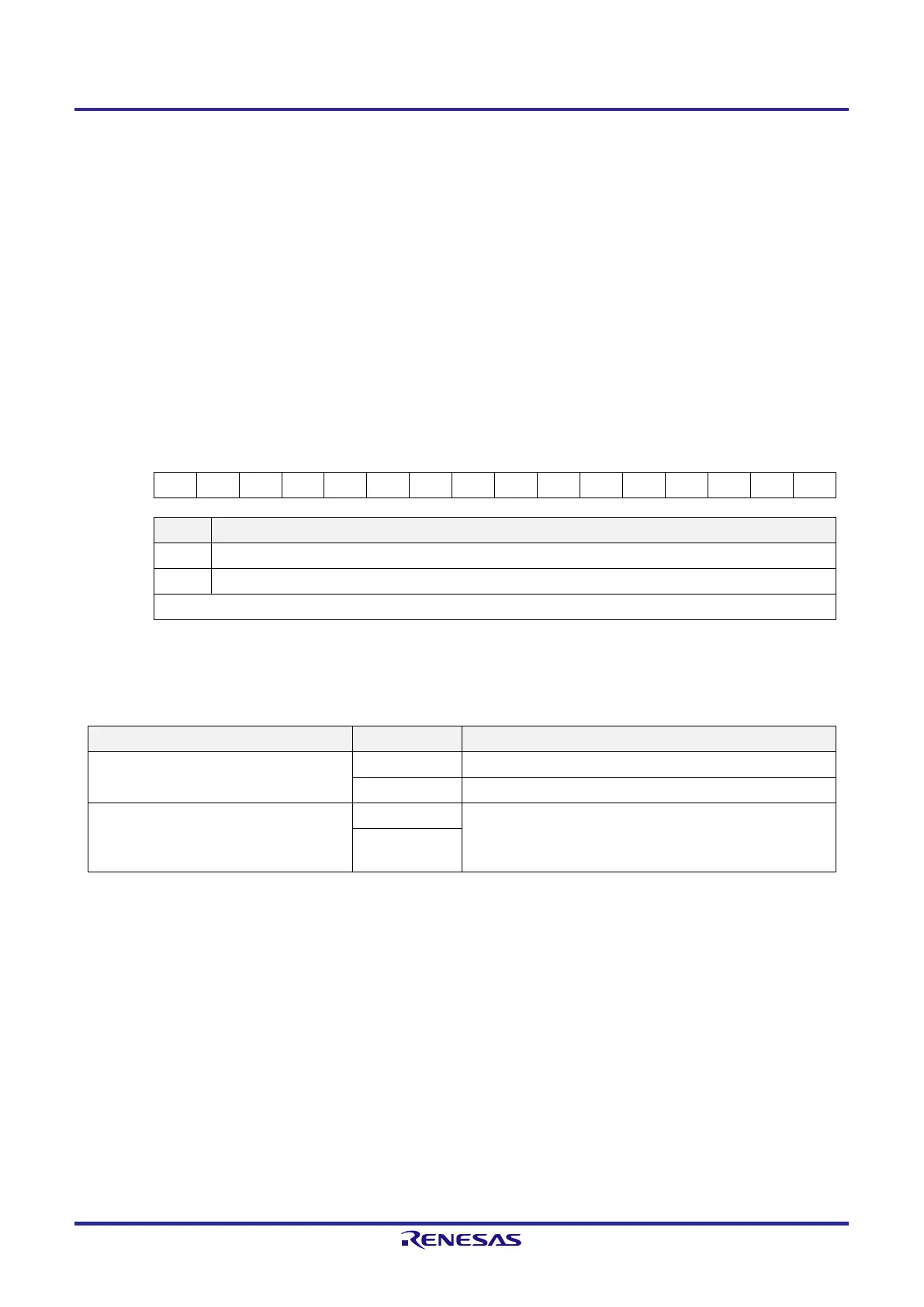
Figure 6-12. Format of Timer Status Register mn (TSRmn)
Address: F01A0H, F01A1H (TSR00) to F01AEH, F01AFH (TSR07) After reset: 0000H R
Symbol 15 14 13 12 11 10 9 8 7 6 5 4 3 2 1 0
TSRmn 0 0 0 0 0 0 0 0 0 0 0 0 0 0 0 OVF
OVF Counter overflow status of channel n
0 Overflow does not occur.
1 Overflow occurs.
When OVF = 1, this flag is cleared (OVF = 0) when the next value is captured without overflow.
Remark m: Unit number (m = 0), n: Channel number (n = 0 to 7)
Table 6-5. OVF Bit Operation and Set/Clear Conditions in Each Operation Mode
Timer operation mode OVF bit Set/clear conditions
●
Capture mode
●
Capture & one-count mode
clear When no overflow has occurred upon capturing
set When an overflow has occurred upon capturing
●
Interval timer mode
●
Event counter mode
●
One-count mode
clear —
(Use prohibited)
set
Remark The OVF bit does not change immediately after the counter has overflowed, but changes upon the
subsequent capture.
 Loading...


