RL78/G15 CHAPTER 12 SERIAL ARRAY UNIT
R01UH0959EJ0110 Rev.1.10 Page 485 of 765
Mar 7, 2023
12.7.1 Address Field Transmission
Address field transmission is a transmission operation that first executes in I
2
C communication to identify the target for
transfer (slave). After a start condition is generated, an address (7 bits) and a transfer direction (1 bit) are transmitted in
one frame.
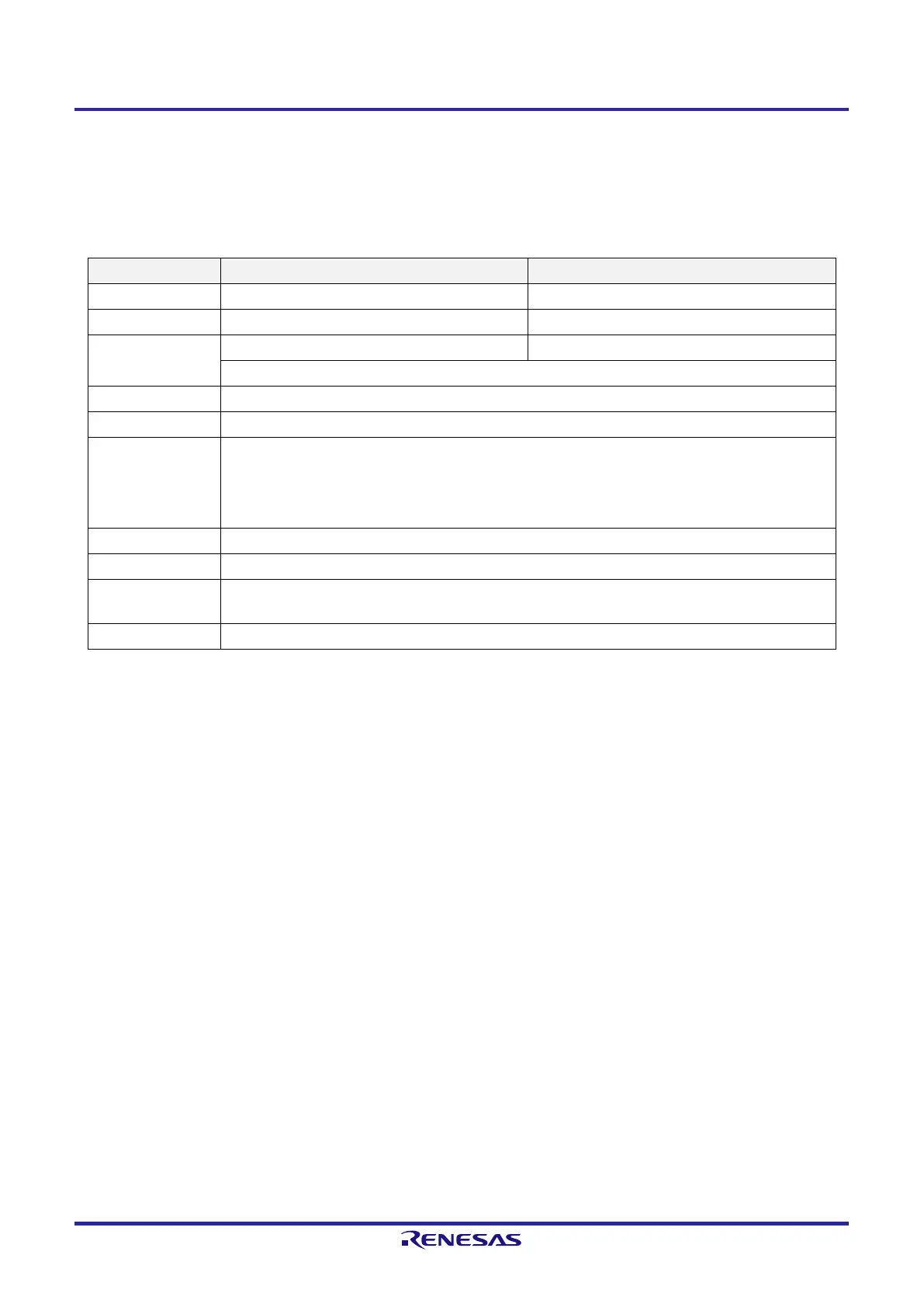
Simplified I
2
C IIC00 IIC01
Target channel Channel 0 of SAU0 Channel 1 of SAU0
Pins used SCL00, SDA00
Note 1
SCL01, SDA01
Note 1
Interrupt INTIIC00 INTIIC01
Transfer end interrupt only (Setting the buffer empty interrupt is prohibited.)
Error detection flag ACK error detection flag (PEFmn)
Transfer data length 8 bits (transmitted with specifying the higher 7 bits as address and the least significant bit as R/W control)
Transfer rate
Note 2
Max. f
MCK
/4 [Hz] (SDRmn[15:9] = 1 or more) f
MCK
: Operation clock frequency of target channel
However, the following condition must be satisfied in each mode of I
2
C.
●
Max. 400 kHz (fast mode)
●
Max. 100 kHz (standard mode)
Data level Non-reverse output (default: high level)
Parity bit No parity bit
Stop bit
Appending 1 bit (for ACK transmission/reception
timing)
Data direction MSB first
Note 1. To perform communication via simplified I
2
C, set the N-ch open-drain output (V
DD
tolerance) mode (POMxx =
1) with the port output mode register (POMxx). See 4.3 Registers Controlling Port Function and 4.5
Register Settings When Using Alternate Function for details.
Note 2. Use this operation within a range that satisfies the conditions above and the peripheral functions
characteristics specified in the electrical characteristics. For details, see CHAPTER 23 ELECTRICAL
SPECIFICATIONS (T
A
= −40 to +85°C) and CHAPTER 24 ELECTRICAL SPECIFICATIONS (T
A
= −40 to
+105°C, T
A
= −40 to +125°C).
Remark m: Unit number (m = 0), n: Channel number (n = 0, 1), mn = 00, 01
 Loading...


