RL78/G15 CHAPTER 12 SERIAL ARRAY UNIT
R01UH0959EJ0110 Rev.1.10 Page 382 of 765
Mar 7, 2023
12.3.7 Serial status register mn (SSRmn)
The SSRmn register indicates the state of communications and occurrence of errors for channel n. The errors indicated
by this register are a framing error, parity error, and overrun error.
The SSRmn register can be read by a 16-bit memory manipulation instruction.
The lower 8 bits of the SSRmn register can be read with an 8-bit memory manipulation instruction with SSRmnL.
The value of each SSRmn register is 0000H following a reset.
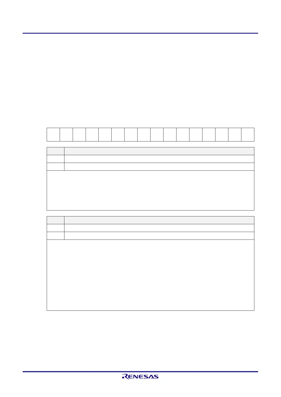
Figure 12-9. Format of Serial Status Register mn (SSRmn) (1/2)
Address: F0100H, F0101H (SSR00) to F0102H, F0103H (SSR01) After reset: 0000H R
Symbol 15 14 13 12 11 10 9 8 7 6 5 4 3 2 1 0
SSRmn 0 0 0 0 0 0 0 0 0
0 0
Note 1
OVFm
n
TSFmn Flag indicating the state of communications for channel n
0 Communication is stopped or suspended.
1 Communication is in progress.
<Clear conditions>
●
The STmn bit of the STm register is set to 1 (communication is stopped) or the SSmn bit of the SSm register is set to 1
(communication is suspended).
●
Communication ends.
<Set condition>
●
Communication starts.
BFFmn Flag indicating the state of the buffer register for channel n
0 Valid data is not stored in the SDRmn register.
1 Valid data is stored in the SDRmn register.
<Clear conditions>
●
Transferring transmit data from the SDRmn register to the shift register ends during transmission.
●
Reading receive data from the SDRmn register ends during reception.
●
The STmn bit of the STm register is set to 1 (communication is stopped) or the SSmn bit of the SSm register is set to 1
(communication is enabled).
<Set conditions>
●
Transmit data is written to the SDRmn register while the TXEmn bit of the SCRmn register is set to 1 (transmission or
transmission/reception mode in each communication mode).
●
Receive data is stored in the SDRmn register while the RXEmn bit of the SCRmn register is set to 1 (reception or
transmission/reception mode in each communication mode).
●
A reception error occurs.
Note 1. The SSR01 register only.
Remark m: Unit number (m = 0), n: Channel number (n = 0, 1)
 Loading...


