RL78/G15 CHAPTER 9 WATCHDOG TIMER
R01UH0959EJ0110 Rev.1.10 Page 315 of 765
Mar 7, 2023
9.4.2 Setting time of watchdog timer
Set the overflow time and interval interrupt time of the watchdog timer by using bits 3 to 1 (WDCS2 to WDCS0) of the
option byte (000C0H).
If an overflow occurs, an internal reset signal is generated. The present count is cleared and the watchdog timer starts
counting again by writing “ACH” to the watchdog timer enable register (WDTE) before the overflow time. When 75% of
the overflow time is reached, an interval interrupt is generated.
The following overflow time and interval interrupt time can be set.
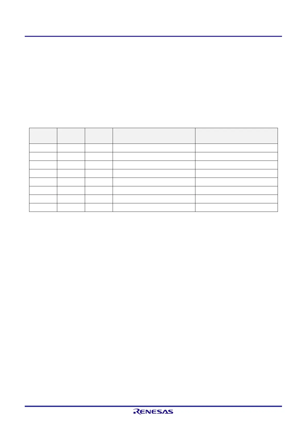
Table 9-3. Setting of Overflow Time and Interval Interrupt Time
WDCS2 WDCS1 WDCS0 Overflow Time of Watchdog Timer
(f
IL
= 17.25 kHz (MAX.))
Interval Interrupt Time of Watchdog Timer
(f
IL
= 17.25 kHz (MAX.))
0 0 0 (2
6
−1)/f
IL
(3.65 ms) 2
6
/f
IL
× 0.75 (2.78 ms)
0 0 1 (2
7
−1)/f
IL
(7.36 ms) 2
7
/f
IL
× 0.75 (5.56 ms)
0 1 0 (2
8
−1)/f
IL
(14.7 ms) 2
8
/f
IL
× 0.75 (11.1 ms)
0 1 1 (2
9
−1)/f
IL
(29.6 ms) 2
9
/f
IL
× 0.75 (22.2 ms)
1 0 0 (2
11
−1)/f
IL
(118 ms) 2
11
/f
IL
× 0.75 (89.0 ms)
1 0 1 (2
13
−1)/f
IL
(474 ms) 2
13
/f
IL
× 0.75 (356 ms)
1 1 0 (2
14
−1)/f
IL
(949 ms) 2
14
/f
IL
× 0.75 (712 ms)
1 1 1 (2
16
−1)/f
IL
(3799 ms) 2
16
/f
IL
× 0.75 (2849 ms)
Caution 1. When operating with the X1 clock
Note 1
after releasing the STOP mode, the CPU starts operating
after the oscillation stabilization time has elapsed.
Therefore, if the period between the STOP mode release and the watchdog timer overflow is short,
an overflow occurs during the oscillation stabilization time, causing a reset.
Consequently, set the overflow time in consideration of the oscillation stabilization time when
operating with the X1 clock
Note 1
after the STOP mode release by an interval interrupt and the
watchdog timer is to be cleared.
Caution 2. The watchdog timer continues counting even after INTWDTI is generated (until ACH is written to
the watchdog timer enable register (WDTE)). If ACH is not written to the WDTE register before the
overflow time, an internal reset signal is generated.
Caution 3. The watchdog timer always generates an interval interrupt when the specified time is reached
unless this is specifically disabled. If the interval interrupt from the watchdog timer is not to be
used, be sure to disable the interrupt by setting the WDTIMK bit to 1.
Remark f
IL
: Low-speed on-chip oscillator clock frequency
Note 1. 16-pin and 20-pin products only
 Loading...


