RL78/G15 CHAPTER 12 SERIAL ARRAY UNIT
R01UH0959EJ0110 Rev.1.10 Page 384 of 765
Mar 7, 2023
12.3.8 Serial channel start register m (SSm)
The SSm is a trigger register that is used to enable starting communication/count by each channel.
When 1 is written to a bit (SSmn) of this register, the corresponding bit (SEmn) of serial channel enable status register m
(SEm) is set to 1 (operation is enabled). Because the SSmn bit is a trigger bit, it is cleared immediately when SEmn = 1.
The SSm register can be set by a 16-bit memory manipulation instruction.
The lower 8 bits of the SSm register can be set with an 1-bit or 8-bit memory manipulation instruction with SSmL.
The value of each SSm register is 0000H following a reset.
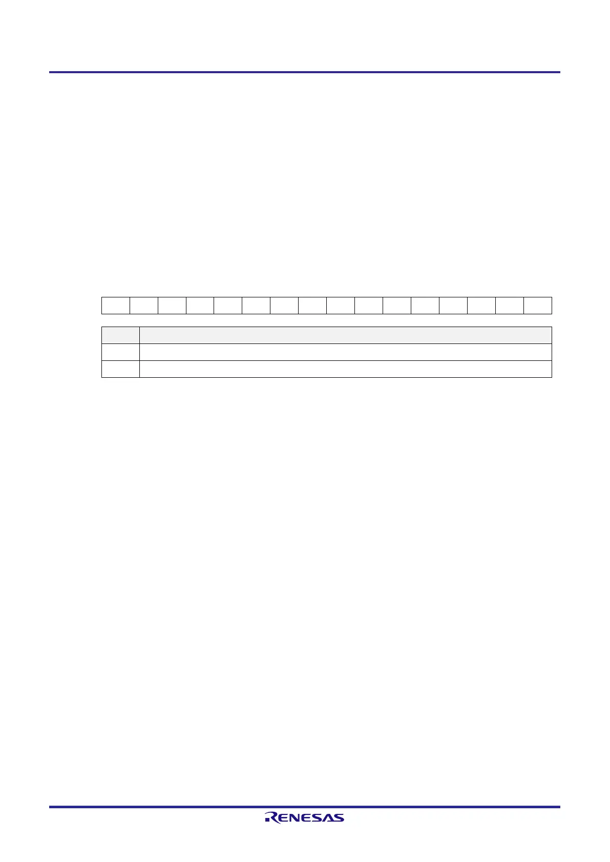
Figure 12-10. Format of Serial Channel Start Register m (SSm)
Address: F0122H, F0123H (SS0) After reset: 0000H R/W
Symbol 15 14 13 12 11 10 9 8 7 6 5 4 3 2 1 0
SS0 0 0 0 0 0 0 0 0 0 0 0 0 0 0 SS01 SS00
SSmn Operation start trigger of channel n
0 No trigger operation
1 Set the SEmn bit to 1 to place the channel in the communications waiting state.
Note 1
Note 1. Setting an SSmn bit to 1 during communications stops communications through channel n and places the
channel in the waiting state. At this time, the values of the control registers and shift register, the states of the
SCKmn and SOmn pins, and the values of the FEFmn, PEFmn, and OVFmn flags are retained.
Caution 1. Be sure to clear bits 15 to 2 of the SS0 register to 0.
Caution 2. For the UART reception, set the RXEmn bit of SCRmn register to 1, and then be sure to set SSmn
to 1 after at least 4 f
MCK
clock cycles have elapsed.
Remark 1. m: Unit number (m = 0), n: Channel number (n = 0, 1)
Remark 2. When the SSm register is read, 0000H is always read.
 Loading...


